Sign In
Upload
Manuals
Brands
GE Manuals
Relays
UR Series L90
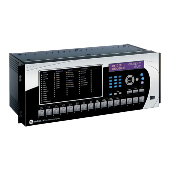
GE UR Series L90 Line Differential Relay Manuals
Manuals and User Guides for GE UR Series L90 Line Differential Relay. We have
1
GE UR Series L90 Line Differential Relay manual available for free PDF download: Instruction Manual
GE UR Series L90 Instruction Manual (846 pages)
Line Current Differential System
Brand:
GE
| Category:
Relays
| Size: 16.5 MB
Table of Contents
Table of Contents
3
1 Getting Started
15
Important Procedures
15
Cautions and Warnings
15
Ur Overview
17
Introduction to the Ur
17
Hardware Architecture
17
Software Architecture
19
Important Concepts
19
Enervista Ur Setup Software
20
Pc Requirements
20
Installation
20
Configuring the L90 for Software Access
21
Using the Quick Connect Feature
24
Connecting to the L90 Relay
30
Ur Hardware
31
Mounting and Wiring
31
Communications
31
Faceplate Display
31
Using the Relay
32
Faceplate Keypad
32
Menu Navigation
32
Menu Hierarchy
32
Relay Activation
32
Relay Passwords
33
Flexlogic Customization
33
Commissioning
34
2 Product Description
35
Introduction
35
Overview
35
Features
37
Ordering
38
Replacement Modules
46
Pilot Channel Relaying
49
Inter-Relay Communications
49
Channel Monitor
50
Loopback Test
51
Direct Transfer Tripping
51
Functionality
52
Protection and Control Functions
52
Metering and Monitoring Functions
52
Other Functions
53
Specifications
54
Protection Elements
54
User-Programmable Elements
59
Monitoring
60
Metering
61
Inputs
62
Power Supply
63
Outputs
63
Communications
64
Inter-Relay Communications
65
Environmental
65
Type Tests
66
Production Tests
66
Approvals
67
Maintenance
67
3 Hardware
69
Description
69
Panel Cutout
69
Module Withdrawal and Insertion
74
Rear Terminal Layout
76
Wiring
77
Typical Wiring
77
Dielectric Strength
78
Control Power
78
Ct/Vt Modules
79
Process Bus Modules
81
Contact Inputs and Outputs
81
Transducer Inputs and Outputs
89
Rs232 Faceplate Port
90
Cpu Communication Ports
90
Irig-B
93
Pilot Channel Communications
94
Description
94
Fiber: Led and Eled Transmitters
95
Fiber-Laser Transmitters
95
Interface
96
Rs422 Interface
99
Two-Channel Two-Clock Rs422 Interface
101
Rs422 and Fiber Interface
101
And Fiber Interface
102
Ieee C37.94 Interface
102
C37.94Sm Interface
106
4 Human Interfaces
109
Enervista Ur Setup Software Interface
109
Introduction
109
Creating a Site List
109
Enervista Ur Setup Overview
109
Enervista Ur Setup Main Window
111
Extended Enervista Ur Setup Features
112
Settings Templates
112
Securing and Locking Flexlogic Equations
116
Settings File Traceability
118
Faceplate Interface
121
Faceplate
121
Led Indicators
122
Custom Labeling of Leds
125
Display
131
Keypad
131
Breaker Control
131
Menus
132
Changing Settings
134
5 Settings
135
Overview
139
Settings Main Menu
139
Fault Reports
139
Introduction to Elements
142
Introduction to Ac Sources
143
Product Setup
146
Security
146
Cybersentry Security
150
Display Properties
156
Clear Relay Records
157
Communications
159
Modbus User Map
188
Real Time Clock
188
Oscillography
196
Data Logger
199
Demand
200
User-Programmable Leds
204
User-Programmable Self-Tests
205
Control Pushbuttons
205
User-Programmable Pushbuttons
207
Flex State Parameters
212
User-Definable Displays
213
Installation
215
Remote Resources Configuration
216
System Setup
217
Ac Inputs
217
Power System
218
Signal Sources
219
Power System
222
Breakers
228
Disconnect Switches
232
Flexcurves
235
Phasor Measurement Unit
242
Flexlogic
265
Introduction to Flexlogic
265
Flexlogic Rules
278
Flexlogic Evaluation
278
Flexlogic Example
279
Flexlogic Equation Editor
283
Flexlogic Timers
283
Flexelements
284
Non-Volatile Latches
288
Grouped Elements
289
Overview
289
Setting Group
289
Line Differential Element
290
Line Pickup
296
Distance
298
Power Swing Detect
316
Load Encroachment
325
Phase Current
327
Neutral Current
337
Wattmetric Ground Fault
345
Ground Current
348
Negative Sequence Current
354
Breaker Failure
360
Voltage Elements
369
Sensitive Directional Power
375
Supervising Elements
379
Control Elements
383
Overview
383
Trip Bus
383
Setting Groups
385
Selector Switch
387
Trip Output
393
Underfrequency
399
Overfrequency
400
Frequency Rate of Change
401
Synchrocheck
403
Digital Elements
407
Digital Counters
410
Monitoring Elements
412
Pilot Schemes
435
Autoreclose
459
Inputs/Outputs
473
Contact Inputs
473
Virtual Inputs
474
Contact Outputs
475
Virtual Outputs
477
Remote Devices
478
Remote Inputs
479
Remote Double-Point Status Inputs
480
Remote Outputs
481
Direct Inputs/Outputs
482
Resetting
484
Iec 61850 Goose Analogs
484
Iec 61850 Goose Integers
485
Transducer Inputs and Outputs
486
Dcma Inputs
486
Rtd Inputs
487
Dcma Outputs
489
Testing
492
Test Mode
492
Force Contact Inputs
493
Force Contact Outputs
494
Channel Tests
495
Phasor Measurement Unit Test Values
495
6 Actual Values
497
Overview
497
Actual Values Main Menu
497
Status
497
Contact Inputs
497
Virtual Inputs
497
Remote Inputs
497
Remote Double-Point Status Inputs
501
Direct Inputs
501
Contact Outputs
501
Virtual Outputs
502
Autoreclose
502
Remote Devices
502
Channel Tests
503
Digital Counters
504
Selector Switches
504
Flex States
505
Ethernet
505
Real Time Clock Synchronizing
505
Iec 61850 Goose Integers
506
Remaining Connection Status
506
Parallel Redundancy Protocol (Prp)
507
Metering Conventions
508
Differential Current
511
Sources
512
Sensitive Directional Power
517
Synchrocheck
517
Tracking Frequency
517
Frequency Rate of Change
517
Flexelements
518
Iec 61580 Goose Analog Values
518
Wattmetric Ground Fault
519
Phasor Measurement Unit
519
Restricted Ground Fault
520
Transducer Inputs and Outputs
520
Records
521
Fault Reports
521
Event Records
521
Oscillography
522
Data Logger
522
Phasor Measurement Unit Records
522
Breaker Maintenance
523
Product Information
524
Model Information
524
Firmware Revisions
524
7 Commands and
525
Commands
525
Commands Menu
525
Virtual Inputs
525
Clear Records
526
Set Date and Time
526
Relay Maintenance
527
Phasor Measurement Unit One-Shot
527
Security
529
Targets Menu
530
Target Messages
530
Relay Self-Tests
530
8 Security
537
User Accounts
537
Overview
537
Enabling the Security Management System
537
Adding a New User
537
Modifying User Privileges
538
Password Requirements
539
Cybersentry
540
Overview
540
Security Menu
541
9 Theory of Operation
547
Overview
547
L90 Design
547
L90 Architecture
547
Removal of Decaying Offset
548
Phaselet Computation
548
Disturbance Detection
549
Fault Detection
549
Ground Differential Element
550
Clock Synchronization
551
Frequency Tracking and Phase Locking
552
Frequency Detection
553
Phase Detection
553
Phase Locking Filter
556
Matching Phaselets
557
Start-Up
557
Hardware and Communication Requirements
557
Online Estimate of Measurement Errors
558
Ct Saturation Detection
559
Charging Current Compensation
559
Differential Element Characteristics
560
Relay Synchronization
561
Operating Condition Characteristics
562
Description
562
Trip Decision Example
564
Trip Decision Test
564
Distance Elements
566
Introduction
566
Phasor Estimation
566
Distance Characteristics
567
Memory Polarization
571
Distance Elements Analysis
572
Phase Distance Applied to Power Transformers
576
Description
576
Example
578
Single-Pole Tripping
580
Overview
580
Phase Selection
583
Communications Channels for Pilot-Aided Schemes
584
Permissive Echo Signaling
592
Pilot Scheme / Phase Selector Coordination
593
Cross-Country Fault Example
594
Overview
595
Single-Ended Fault Locator
601
10 Application of Settings
605
Ct Requirements
605
Introduction
605
Calculation Example 1
605
Calculation Example 2
606
Current Differential (87L) Settings
607
Introduction
607
Current Differential Pickup
607
Current Diff Restraint 1
607
Current Diff Restraint 2
607
Current Diff Break Point
607
Ct Tap
608
Breaker-And-A-Half
610
Distributed Bus Protection
613
Channel Asymmetry Compensation Using Gps
614
Description
614
Compensation Method 1
614
Compensation Method 2
615
Compensation Method 3
615
Distance Backup/Supervision
617
Description
617
Phase Distance
618
Ground Distance
619
Protection Signaling Schemes
621
Overview
621
Direct Under-Reaching Transfer Trip (Dutt)
621
Permissive Under-Reaching Transfer Trip (Putt)
621
Permissive Over-Reaching Transfer Trip (Pott)
621
Hybrid Pott Scheme (Hyb-Pott)
622
Directional Comparison Blocking
623
Directional Comparison Unblocking
624
Series Compensated Lines
626
Distance Settings on Series Compensated Lines
626
Ground Directional Overcurrent
627
Description
628
Lv-Side Faults
629
External Ground Faults
629
Instantaneous Elements
630
Instantaneous Element Error During L90 Synchronization
630
Phase Distance through Power Transformers
631
Phase Distance Protection
631
Example
632
11 Commissioning
633
Testing
633
Channel Testing
633
Clock Synchronization Tests
634
Current Differential
635
Local-Remote Relay Tests
636
Parameter Lists
637
Flexanalog Items
637
A.1.1 Flexanalog Items
637
Flexinteger Items
651
A.1.2 Flexinteger Items
651
Modbus Rtu Protocol
653
Introduction
653
Physical Layer
653
Data Link Layer
653
B.1.1 Introduction
653
Algorithm
654
B.1.4 Crc-16 Algorithm
654
Modbus Function Codes
655
Supported Function Codes
655
Read Actual Values or Settings (Function Code 03/04H
655
Execute Operation (Function Code 05H
656
Store Single Setting (Function Code 06H
656
Store Multiple Settings (Function Code 10H
657
Exception Responses
657
File Transfers
658
Obtaining Relay Files Via Modbus
658
Modbus Password Operation
659
Memory Mapping
661
Modbus Memory Map
661
Data Formats
732
B.4.2 Data Formats
732
Iec 61850
773
Overview
773
Introduction
773
Communication Profiles
773
C.1.1 Introduction
773
Server Data Organization
774
Overview
774
Ggio1: Digital Status Values
774
Ggio2: Digital Control Values
774
Ggio3: Digital Status and Analog Values from Received Goose Data
774
Ggio4: Generic Analog Measured Values
774
C.2.1 Overview
774
Mmxu: Analog Measured Values
775
Protection and Other Logical Nodes
775
Server Features and Configuration
777
Buffered/Unbuffered Reporting
777
File Transfer
777
Timestamps and Scanning
777
Logical Device Name
777
Location
777
Logical Node Name Prefixes
778
Connection Timing
778
Non-Iec 61850 Data
778
Communication Software Utilities
778
Overview
779
Gsse Configuration
779
Fixed Goose
779
Configurable Goose
779
C.4.1 Overview
779
Ethernet Mac Address for Gsse/Goose
782
Gsse ID and Goose ID Settings
782
Iec 61850 Implementation Via Enervista Ur Setup
783
Overview
783
C.5.1 Overview
783
Configuring Iec 61850 Settings
784
About ICD Files
785
Creating an ICD File with Enervista Ur Setup
789
About Scd Files
789
Importing an Scd File with Enervista Ur Setup
792
Acsi Conformance
794
Acsi Basic Conformance Statement
794
Acsi Models Conformance Statement
794
Acsi Services Conformance Statement
795
Logical Nodes
798
Logical Nodes Table
798
Iec 60870-5-104
803
Interoperability Document
803
D.1.1 Interoperability Document
803
Point List
811
D.1.2 Point List
811
Device Profile Document
813
Dnp V3.00 Device Profile
813
E.1.2 Implementation Table
816
Dnp Point Lists
820
Binary Input Points
820
Binary and Control Relay Output
821
Counters
822
E.2.3 Counters
822
Analog Inputs
823
E.2.4 Analog Inputs
823
Change Notes
825
Revision History
825
F.1.1 Revision History
825
Changes to the L90 Manual
826
Abbreviations
829
Standard Abbreviations
829
F.2.1 Standard Abbreviations
829
F.3.1 Ge Multilin Warranty
833
Warranty
834
Advertisement
Advertisement
Related Products
GE UR series
GE UR Switch Module Ethernet Communications Switch
GE Multilin UR-2S
GE Multilin UR-2T
GE UR F35 Series
GE UR T60
GE UR Series C70
GE UVD-IP-EVRDNR
GE UCG1600L
GE UUC136WCDBA
GE Categories
Refrigerator
Ranges
Microwave Oven
Air Conditioner
Dishwasher
More GE Manuals
Login
Sign In
OR
Sign in with Facebook
Sign in with Google
Upload manual
Upload from disk
Upload from URL