Sign In
Upload
Manuals
Brands
GE Manuals
Protection Device
UR Series C70
User Manuals: GE UR Series C70 Protection System
Manuals and User Guides for GE UR Series C70 Protection System. We have
1
GE UR Series C70 Protection System manual available for free PDF download: Instruction Manual
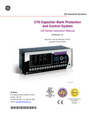
GE UR Series C70 Instruction Manual (614 pages)
Capacitor Bank Protection and Control System
Brand:
GE
| Category:
Protection Device
| Size: 10.64 MB
Table of Contents
Table of Contents
3
Cautions and Warnings
11
Introduction to the Ur
12
1.2 Ur Overview
13
Hardware Architecture
13
Software Architecture
14
1.3 Enervista Ur Setup Software
15
Pc Requirements
15
Configuring the C70 for Software Access
16
Using the Quick Connect Feature
19
Connecting to the C70 Relay
25
1.4 Ur Hardware
26
Mounting and Wiring
26
1.5 Using the Relay
27
Faceplate Keypad
27
Relay Passwords
28
Commissioning
29
Overview
31
Ordering
33
Replacement Modules
36
2.2 Specifications
39
Protection Elements
39
User-Programmable Elements
42
Monitoring
43
Inputs
44
Outputs
45
D. Iec 60870-5-104
46
Communications
46
Inter-Relay Communications
48
Type Tests
49
Approvals
50
3.1 Description
51
Panel Cutout
51
Module Withdrawal and Insertion
56
Rear Terminal Layout
58
3.2 Wiring
59
Typical Wiring
59
Dielectric Strength
60
Ct/Vt Modules
61
Process Bus Modules
63
Transducer Inputs/Outputs
71
Rs232 Faceplate Port
72
Cpu Communication Ports
72
Irig-B
76
Direct Input/Output Communications
77
Description
77
Fiber: Led and Eled Transmitters
79
Interface
80
Rs422 Interface
83
Ieee C37.94 Interface
85
Managed Ethernet Switch Modules
88
Overview
88
Managed Ethernet Switch Module Hardware
88
Managed Switch Led Indicators
89
Configuring the Managed Ethernet Switch Module
89
Uploading C70 Switch Module Firmware
92
Ethernet Switch Self-Test Errors
94
Human Interfaces
95
Enervista Ur Setup Interface
95
Introduction
95
Creating a Site List
95
Enervista Ur Setup Overview
95
Enervista Ur Setup Main Window
97
Extended Enervista Ur Setup Features
98
Settings Templates
98
Securing and Locking Flexlogic™ Equations
102
Settings File Traceability
104
Faceplate Interface
107
Faceplate
107
Led Indicators
108
Custom Labeling of Leds
111
Display
116
Keypad
116
Breaker Control
117
Menus
118
Changing Settings
120
Settings
125
Overview
125
Settings Main Menu
125
Introduction to Elements
128
Introduction to Ac Sources
129
Product Setup
132
Security
132
Display Properties
136
Clear Relay Records
138
Communications
139
Modbus User Map
159
Real Time Clock
160
User-Programmable Fault Reports
161
Oscillography
162
Data Logger
164
User-Programmable Leds
166
User-Programmable Self Tests
169
Control Pushbuttons
170
User-Programmable Pushbuttons
171
Flex State Parameters
176
User-Definable Displays
177
Direct Inputs/Outputs
179
Installation
187
5.3 Remote Resources
188
Remote Resources Configuration
188
System Setup
189
Ac Inputs
189
Power System
190
Signal Sources
192
Breakers
194
Flexcurves
201
Flexlogic
208
Introduction to Flexlogic
208
Flexlogic™ Rules
218
Flexlogic™ Evaluation
218
Flexlogic™ Example
219
Flexlogic Equation Editor
223
Flexlogic Timers
223
Flexelements
224
Non-Volatile Latches
228
Grouped Elements
229
Overview
229
Setting Group
229
Breaker Failure
229
Breaker Failure
230
Phase Current
239
Neutral Current
252
Ground Current
264
Voltage Elements
267
Control Elements
286
Overview
286
Trip Bus 1
286
Setting Groups
288
Selector Switch
289
Time of Day Timers
295
Capacitor Control
296
Automatic Voltage Regulator
301
Digital Elements
306
Digital Counters
309
Monitoring Elements
311
Status
313
Contact Inputs
320
Virtual Inputs
322
Contact Outputs
323
Virtual Outputs
325
Remote Devices
326
Remote Inputs
327
Remote Double-Point Status Inputs
328
Resetting
329
Direct Inputs and Outputs
330
Iec 61850 Goose Analogs
333
Iec 61850 Goose Integers
334
5.9 Transducer Inputs and Outputs
335
Dcma Inputs
335
Rtd Inputs
336
Dcma Outputs
338
5.10 Testing
341
Test Mode
341
Force Contact Inputs
342
Force Contact Outputs
343
6.1 Overview
345
Actual Values Main Menu
345
Contact Inputs
347
Contact Outputs
348
Virtual Outputs
348
Remote Double-Point Status Inputs
348
Remote Devices
349
Digital Counters
349
Selector Switches
350
Time of Day Timers
350
Flex States
350
Ethernet
350
Direct Inputs
351
Direct Devices Status
351
Iec 61850 Goose Integers
352
Ethernet Switch
352
6.3 Metering
353
Metering Conventions
353
Sources
356
Capacitor Control
360
Capacitor Bank
361
Tracking Frequency
362
Flexelements
362
Iec 61580 Goose Analog Values
363
Transducer Inputs/Outputs
363
Records
364
User-Programmable Fault Reports
364
Event Records
364
Oscillography
364
Data Logger
365
Product Information
366
Model Information
366
Firmware Revisions
366
Commands and
367
Commands
367
Commands Menu
367
Capacitor Bank Automatic Settings
367
Virtual Inputs
372
Clear Records
372
Set Date and Time
372
Relay Maintenance
373
Targets Menu
374
Target Messages
374
Relay Self-Tests
374
7.2 Targets
374
Security
379
Password Security
379
Overview
379
Password Security Menu
380
Local Passwords
380
Remote Passwords
381
Access Supervision
381
Dual Permission Security Access
382
Settings Security
384
Settings Templates
384
Securing and Locking Flexlogic™ Equations
388
Settings File Traceability
390
Enervista Security Management System
393
Overview
393
Enabling the Security Management System
393
Adding a New User
393
Modifying User Privileges
394
Theory of Operation
397
Overview
397
General Operation
397
Bank Phase Overvoltage (Ansi 59B)
397
Voltage Differential (Ansi 87V)
399
Compensated Bank Neutral Voltage Unbalance (Ansi 59Nu)
402
Phase Current Unbalance (Ansi 60P)
406
Neutral Current Unbalance (Ansi 60N)
408
10 Application of 10.1 Arrangement of Shunt Capacitor Banks
412
Settings
412
Overview
415
Externally Fused Capacitors
415
Internally Fused Capacitors
415
Fuseless Capacitors
415
Fuseless Capacitors
416
Unfused Capacitors
416
Connections of Shunt Capacitor Banks
417
Grounded Wye-Connected Banks
417
Ungrounded Wye-Connected Banks
417
Delta-Connected Banks
417
H-Configuration
417
Tapped Configuration
417
Summary
418
Protection Methods for Capacitor Banks
419
Description
419
Capacitor Unbalance Protection
419
Protection for Rack Faults (Arc-Over Within Capacitor Bank)
424
Overvoltage
424
Overcurrent
425
Loss of Bus Voltage
425
Setting Example
426
Description
426
Vt and Ct Setup
426
Source Assignment
427
Bank Unbalance Calculations
428
Bank Voltage Differential Settings
430
Bank Phase Current Unbalance Settings
432
Bank Phase Overvoltage Settings
433
Bank Phase Undervoltage Settings
434
Bank Overcurrent Protection
435
Parameter Lists
437
Flexanalog Items
437
A.1.1 Flexanalog Items
437
Flexinteger Items
468
A.1.2 Flexinteger Items
468
B. Modbus
469
Communications
469
Introduction
469
Physical Layer
469
Data Link Layer
469
B.1.1 Introduction
469
Algorithm
470
B.1.4 Crc-16 Algorithm
470
Modbus Rtu Protocol
469
Modbus Function Codes
471
Supported Function Codes
471
Read Actual Values or Settings (Function Code 03/04H
471
Execute Operation (Function Code 05H
471
Execute Operation (Function Code 05H
472
Store Single Setting (Function Code 06H
472
Store Multiple Settings (Function Code 10H
473
Exception Responses
473
File Transfers
474
Obtaining Relay Files Via Modbus
474
Modbus Password Operation
475
Memory Mapping
476
Data Formats
529
C.1 Overview
549
Iec 61850
549
Communications
549
Introduction
549
Communication Profiles
549
C.1.2 Communication Profiles
549
Server Data Organization
550
Overview
550
Ggio1: Digital Status Values
550
Ggio2: Digital Control Values
550
Ggio3: Digital Status and Analog Values from Received Goose Datac-2
550
Ggio4: Generic Analog Measured Values
550
C.2.1 Overview
550
Mmxu: Analog Measured Values
551
Protection and Other Logical Nodes
551
Server Features and Configuration
553
Buffered/Unbuffered Reporting
553
File Transfer
553
Timestamps and Scanning
553
Logical Device Name
553
Location
553
Logical Node Name Prefixes
554
Connection Timing
554
Non-Iec 61850 Data
554
Communication Software Utilities
554
Generic Substation Event Services: Gsse and Goose
555
Overview
555
Gsse Configuration
555
Fixed Goose
555
Configurable Goose
555
C.4.1 Overview
555
Ethernet Mac Address for Gsse/Goose
557
Gsse ID and Goose ID Settings
558
Iec 61850 Implementation Via Enervista Ur Setup
559
Overview
559
C.5.1 Overview
559
Configuring Iec 61850 Settings
560
About ICD Files
561
Creating an ICD File with Enervista Ur Setup
565
About Scd Files
565
Importing an Scd File with Enervista Ur Setup
568
Acsi Conformance
570
Acsi Basic Conformance Statement
570
Acsi Models Conformance Statement
570
Acsi Services Conformance Statement
571
Logical Nodes
574
Logical Nodes Table
574
D.1 Overview
577
Interoperability Document
577
D.1.1 Interoperability Document
577
Point List
585
D.1.2 Point List
585
Device Profile Document
587
Dnp V3.00 Device Profile
587
E.1.2 Implementation Table
590
Dnp Point Lists
594
Binary Input Points
594
Binary and Control Relay Output
595
Counters
596
E.2.3 Counters
596
Analog Inputs
597
E.2.4 Analog Inputs
597
Change Notes
599
Changes to the C70 Manual
599
F.1.1 Revision History
599
Abbreviations
604
Standard Abbreviations
604
F.2.1 Standard Abbreviations
604
Warranty
606
Ge Multilin Warranty
606
F.3.1 Ge Multilin Warranty
606
Advertisement
Advertisement
Related Products
GE UR F35 Series
GE UR T60
GE UR Switch Module Ethernet Communications Switch
GE Multilin UR-2S
GE Multilin UR-2T
GE UR series
GE UR Series L90
GE UVW8361
GE UF 209
GE UF 207
GE Categories
Refrigerator
Ranges
Microwave Oven
Air Conditioner
Dishwasher
More GE Manuals
Login
Sign In
OR
Sign in with Facebook
Sign in with Google
Upload manual
Upload from disk
Upload from URL