Sign In
Upload
Manuals
Brands
GE Manuals
Measuring Instruments
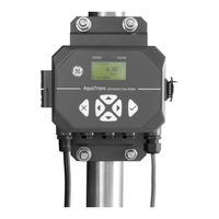
AquaTrans ST600
GE AquaTrans ST600 Manuals
Manuals and User Guides for GE AquaTrans ST600. We have
1
GE AquaTrans ST600 manual available for free PDF download: User Manual
GE AquaTrans ST600 User Manual (216 pages)
ultrasonic flow meter
Brand:
GE
| Category:
Measuring Instruments
| Size: 9.14 MB
Table of Contents
Table of Contents
5
Product Registration
9
Safety Issues
9
Services
9
Terms and Conditions
9
Typographical Conventions
9
Auxiliary Equipment
10
Environmental Compliance
11
Chapter 1. General Installation Instructions
13
Introduction
13
Theory of Operation
14
Safety Guidelines
15
Unpacking the AT600 System
16
Installing the Electronics Enclosure
17
Calculating the Transducer Spacing
18
Choosing a Clamp-On Fixture/Transducer Location
19
Mounting the Clamp-On Fixture and Transducer System
20
Chapter 2. Clamp-On Fixture and Transducer Installation
23
Installing an AT600 Clamp-On Fixture and Transducer System
23
Transducer Spacing = 32 to 250 MM or 50 to 320 MM, Traverses = 2, Fixtures = 1
24
Transducer Spacing = 320 to 940 MM, Traverses = 2, Fixtures = 2
26
Transducer Spacing = 0 to 250 MM or 0 to 320 MM, Traverses = 1, Fixtures = 2
29
Transducer Spacing >320 MM, Traverses = 1, Fixtures = 2
31
Installing a CF-ES Clamp-On Fixture and Transducer System
32
Installing a General Clamping Fixture and Transducer System
32
Installing C-RS or C-PT Transducers with an RG316 Cable
32
Installing C-RS or C-PT Transducers with an RG62 Cable
33
Chapter 3. Wiring the AT600 Electronics
35
Wiring Diagram
35
Wiring the Line Power
37
Wiring the Transducers
38
Wiring the System Ground
39
Wiring the Analog Output for HART Communication
39
Wiring the Modbus Communication
40
Wiring the Frequency/Totalizer/Alarm Output
41
Wiring the Gate Input
42
Chapter 4. Initial Setup and Programming
43
Introduction
43
AT600 Keypad Operation
44
Display Programming
45
Changing the Display for One- or Two-Variable Screens
45
Changing the Measurement Type for One- or Two-Variable Screens
46
Changing the Measurement Type or Units for the Totalizer Screens
47
Starting or Stopping the Totalizer Measurement
49
Resetting the Totalizer
50
Entering the Main Menu
51
Display Format
51
Keypad Lockout
52
Language
53
Program and Program Review Menus
53
User Preferences
55
Setting
55
Units Setting
56
Density
57
Password
58
Display
58
Inputs/Outputs
60
Programming the Analog Output Menu
60
Programming the Digital Output Menu
63
Programming the Modbus/Service Port
73
Programming Digital Communications
73
Sensor Setup
78
Meter Setup
79
Mounting Type
80
Programming the Pipe Menu When Wetted Selected
81
Programming the Pipe Menu When Clamp-On Selected
82
Programming the Transducer When Clamp-On Selected
86
Programming the Transducer When Wetted Selected
92
Programming the Number of Traverses
95
Programming the Fluid Type
96
Programming the Fluid Temperature
97
Calculating the Path When Clamp-On Selected
98
Enter the Path When Wetted Selected
99
Chapter 5. Error Codes and Troubleshooting
101
Error Display in the User Interface
101
Error Header
101
Flow Error String
101
Diagnostics
105
Introduction
105
Flowcell Problems
105
Chapter 6. Communication
109
Modbus
109
Introduction
109
MODBUS Register Map
109
Hart
117
Device Identification
117
Commands
117
Additional Device Status
178
Device Variables
179
HART Engineering Units
180
Appendix A. Specifications
185
Overall Operation and Performance
185
Electronics
186
Clamp-On Ultrasonic Flow Transducers
187
General
189
Wiring Cable Specifications and Requirements
189
Cable Fixing Requirement and Gland Torque
189
Display Languages
189
Product Models
189
Appendix B. Data Records
191
Service Record
191
Data Entry
191
Initial Settings
192
Diagnostic Parameters
193
Appendix C. Updating the Firmware in the Field
195
Introduction
195
System Requirements
195
Preparation
195
Performing the Firmware Update
196
Check the Current Firmware Version
196
Update Steps
196
Clearing an S2 Warning
198
Support
198
Appendix D. Menu Maps
199
The Display Measurement Menu
199
The Main Menu
200
The Main Menu > User Preferences Menu
201
The Main Menu > Inputs/Outputs Menu
202
The Main Menu > Sensor Setup Menu
203
D.6 the Main Menu > Calibration Menu
204
D.7 the Main Menu > Advanced Menu
205
D.8 the Main Menu > Factory Menu
206
Advertisement
Advertisement
Related Products
GE SimpliNano
GE SCOUT100-Ex
GE SCOUT140-Ex
GE Sievers 900 Series
GE StressTel T-MIKE E
GE Centricity SP1001
GE SS-131ER
GE SEER 1000
GE AquaTrans AT600
GE Digital Energy STS-400-63-3
GE Categories
Refrigerator
Ranges
Microwave Oven
Air Conditioner
Dishwasher
More GE Manuals
Login
Sign In
OR
Sign in with Facebook
Sign in with Google
Upload manual
Upload from disk
Upload from URL