Advertisement
Quick Links
Advertisement

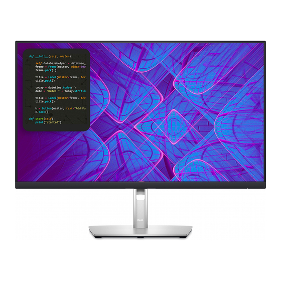
Summary of Contents for Dell P2723QE
- Page 1 Service Manual Service Manual LCD Monitor P2723QE...
- Page 2 Service Manual Service Manual Versions and Revision Version Release Date Revision 2022/02/14 Initial Release...
- Page 3 Service Manual 1. Important Safety Notice Product Announcement: of PWBA, not solder side. This product is certificated to meet RoHS ! To ensure using a proper screwdriver, follow Directive and Lead-Free produced definition. the torque and force listed in assembly and Using approved critical components only is disassembly procedures to unscrew screws.
- Page 4 Service Manual 2. Exploded view diagram with list of items...
- Page 5 Service Manual NOTE: For replacement of power cord, connectivity cable and external power supply (if applicable), contact Dell: 1. Go to https://www.dell.com/support. 2. Verify your country or region in the Choose A Country/Region drop-down menu at the bottom-right corner of the page.
- Page 6 Service Manual 3. Wiring Connectivity Diagram...
- Page 7 Service Manual 4. How to connect and disconnect power cable/connectivity cable WARNING: To change power cable/ connectivity cable, switch off power before unplugging the cable and replugging in required cable.
- Page 8 Service Manual...
- Page 9 Service Manual...
-
Page 10: Disassembly Procedure
Service Manual 5. Disassembly Procedure 1. Remove Rear Cover Screw 4. Remove Keypad: Remove screws “1~4” on rear cover with electric Remove keypad cable in sequence of “1, 2, 3” screwdriver. Torque: 12.0 ± 0.5Kgf/cm Remove screws “5, 6” with electric screwdriver. Screwdriver torque: 2.5 ±... - Page 11 Service Manual 7. Remove FFC: 10. Remove Front Trim Screws 1: Remove aluminium foil “1” Remove screws “1~11” on mid frame with b. Lift up FFC cover, grasp on pinch, then remove electric screwdriver. Screwdriver torque: 3.5 ± light bar cable horizontally 0.5 Kgf/cm b.
- Page 12 Service Manual Remove electrolyte capacitor >25mm height (red Take out the capacitor pin solder with soldering iron. mark) from printed circuit boards. Lift the bulk capacitor away from power board. Cut the glue between bulk cap and PCBA with knife – ensure cutting path within the glue, don’t touch bulk cap and PCBA.
-
Page 13: Troubleshooting Instructions
Service Manual 6. Trouble Shooting Instructions Self-test Your monitor provides a self-test feature that allows you to check whether your monitor is functioning properly. If your monitor and computer are properly connected but the monitor screen remains dark, run the monitor self-test by performing the following steps: 1. - Page 14 Service Manual Trouble Shooting Instructions Your monitor has a built-in diagnostic tool that helps you determine if the screen abnormality you are experiencing is an inherent problem with your monitor, or with your computer and video card. To run the built-in diagnostics: To run the built-in diagnostics: Ensure that the screen is clean (no dust particles on the surface of the screen).
-
Page 15: Common Problems
Service Manual Trouble Shooting Instructions Common problems The following table provides general information about common monitor problems you might encounter and the possible solutions:... - Page 16 Service Manual Trouble Shooting Instructions...
- Page 17 Service Manual Trouble Shooting Instructions...
- Page 18 Service Manual Trouble Shooting Instructions...
- Page 19 Service Manual Trouble Shooting Instructions...
- Page 20 Service Manual Trouble Shooting Instructions...


