Sign In
Upload
Manuals
Brands
Mitsubishi Electric Manuals
Touch terminals
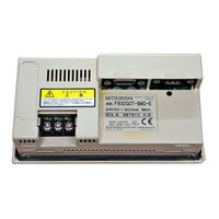
F943GOT-SBD-H-E
Mitsubishi Electric F943GOT-SBD-H-E Manuals
Manuals and User Guides for Mitsubishi Electric F943GOT-SBD-H-E. We have
1
Mitsubishi Electric F943GOT-SBD-H-E manual available for free PDF download: Hardware Manual
Mitsubishi Electric F943GOT-SBD-H-E Hardware Manual (592 pages)
GOT-F900 SERIES GRAPHIC OPERATION TERMINAL
Brand:
Mitsubishi Electric
| Category:
Touch terminals
| Size: 14.86 MB
Table of Contents
Table of Contents
9
1 Introduction
17
Rank and Use Method of this Manual
17
Classification of Manuals in Accordance with Purpose
19
Abbreviations, Generic Names and Terms Used in this Manual
23
Types and Names of GOT-F900 Series
23
Information Offered by Model Name
24
In-Built Fonts of Graphic Operation Terminal (Japanese/Overseas Product)
25
Abbreviation List
26
2 Outline
29
Connection Type Supported by GOT-F900
29
GOT Type List and Index
29
Connection Type List and Index
30
Outline of Connection Types
31
PLC by Mitsubishi
31
PLC by Other Companies
35
Others
37
3 Specifications
39
OS Version and Correspondence to Connected Equipment of GOT-F900
39
How to Confirm os Version of GOT-F900
39
PLC, Positioning Unit, Inverter Manufactured by Mitsubishi
40
PLC Manufactured by Other Companies
42
Others
44
Version of Screen Creation Software and Correspondence to GOT-F900
45
How to Conform Version of Screen Creation Software
46
Screen Creation Software Version Corresponding to GOT-F900 Series
48
Screen Creation Software Corresponding to each Connected Equipment
49
Device Names Which Can be Monitored
51
Devices in GOT-F900
51
PLC by Mitsubishi
52
PLC Units Manufactured by Other Companies
58
Hardware Specifications
66
4 Installation and Wiring of F920GOT-K/F930GOT(-K)/F940(W)GOT
71
Outline of Connection
74
Name of each Part
75
Front Panel
75
Rear Panel
75
Function of Ports
76
Outside Dimensions and Panel Face Processing
78
Panel Cut Dimension
78
Installation
79
Caution on Installation
79
Inner Dimension of the Panel Required for Installation
80
Installation Procedure
83
Connector Pin Layout and Signal Name (Excluding the 5 V Type F920GOT
84
Outline of Internal Wiring
85
Wiring for 24V DC and 5V DC Power Supply and Class D Grounding
86
Handling of Function Keys (F1 to F8) (F920GOT-K and F930GOT-K)
89
Use of Function Keys
90
Preparation of Function Key Name Sheet (Available in the F930GOT-K)
91
Cautions on Use
92
Label Pattern (F930GOT-K)
93
Setting of Connected Equipment for GOT
94
5 Installation and Wiring of Handy GOT
103
Outline of Connection
107
Handy GOT (Excluding RH Model)
107
Handy GOT (RH Model)
109
Name of each Part
110
Front Panel
110
Rear Panel and Connectors
111
Outside Dimensions and Installation
112
Outside Dimensions
112
Installation
114
Selection and Installation of External Cable
116
Handy GOT (Excluding RH Model)
116
Wiring between Handy GOT (RH Model) Operation Switches and Connected Equipment
118
Installation of External Cable
120
Processing Panel Face of Control Box or Cabinet
122
Selection of Relay Cable
122
Appearance Shape of Relay Cable
124
Panel Cut Dimension for Relay Cable
130
Panel Cut Dimension for F9GT-HCNB
130
Pin Layout and Signal Allocation of Connector for Serial Communication and Operation Switches
131
F9GT-Hcabo-Om/F9Gt-HCAB1-Om External Cable
131
F9GT-RHCAB-Om External Cable
132
Outline of Internal Wiring
133
Wiring for 24V DC Power Supply and Class D Grounding
135
Wiring and Handling of Operation Switches SW1 to SW4
136
Handling of Operation Switches
136
Preparation of Operation Switch Name Sheet
138
Wiring and Handling of Emergency Stop Switch (ES1)
140
Handling of Grip Switch (Excluding RH Model)
142
Function of Grip Switch
142
Setting in Main Unit and Screen Creation Software
142
Grip Switch Operation Specifications
143
Communication with Connected Equipment (Grip Switch ON/OFF Signal)
146
Handling of Grip Switch (RH Model Only)
148
Wiring of Grip Switch
148
Setting of Grip Switch LED
149
LED Action
149
Handling of Keylock Switch (RH Model Only)
150
Setting of Connected Equipment for GOT
151
Connection Diagram of Handy GOT Operation Switches and Power Supply
157
Connector Conversion Box F9GT-HCNB
159
Outline of Product
159
Name of each Part
159
Specifications
160
Installation
161
F9GT-HCNB Conversion Box
163
Diagnostic
164
F940GOT Handy (F94*GOT-*BD-H-E)
164
F940GOT Handy (F94*GOT-*BD-RH-E)
165
How to Read Manual for Handy GOT RH Model
166
6 Connection of Peripheral Equipment (Screen Data Transfer/Sequence Program Transfer and Monitor)
167
Outline of Connection
167
Connection to Personal Computer
169
Screen Data Transfer
169
Sequence Program Transfer (Two-Port Interface Function Built)
170
Cable Connection Procedure
171
Connection of F943 Handy GOT (for PLC) and Personal Computer
173
Outline
173
Configuration to Transfer Screen Data Using PLC Connector
173
Changeover of Connection between PLC and Personal Computer
174
Caution on Use of Peripheral Equipment
175
Caution When Connecting the GOT and PLC Via RS-232C Port (Only in Case of the F920GOT-K, F930GOT, F930GOT-K, or F940GOT)
175
Caution When Transferring Screen Data to the F920GOT-K (5V Type)
176
Cable Diagram
178
Cable for Personal Computer
178
Troubleshooting
179
7 Connection of Two or more GOT Units
181
System Condition
181
Connection Configuration for Two or more GOT Units
182
Configuration When First GOT Unit Is Connected through RS-422
182
When First GOT Unit Is Connected through RS-232C
184
When Connection Is Changed from RS-422 to RS-232C
185
Rules in Configuration
186
Connection Method
186
Communication Port Number Table
187
Connection Concept in each Model Name
187
Connection of Four or more Display Units
188
Cautions on Connecting Two or more GOT Units
190
Power on Sequence
190
Transfer of Sequence Program and Use of Monitor
191
Setting of Connected Equipment for GOT
192
Connection Type (RS-422/RS-232C Setting)
192
Station Number Setting
192
Setting Procedure
193
Cable Diagram
205
Troubleshooting
205
8 Connection of MELSEC-F FX Series PLC
205
System Condition
205
System Configuration
206
Configuration for CPU Direct Connection (RS-422)
206
Configuration for CPU Direct Connection (RS-232C)
208
Cautions on Use of MELSEC-F FX Series
210
Device Specification
210
Devices Which Can be Monitored
210
When GOT-F900 Is Connected to Optional Port
210
Restrictions in Connecting Two or more F920GOT-K (5V Type) Units to FX Series PLC
213
Setting of Connected Equipment for GOT
214
9 Connection of MELSEC-A Series PLC
231
System Condition
231
System Configuration
231
Configuration for Direct Connection (RS-422)
233
Configuration for a Computer Link Connection (RS-422)
235
Configuration for a Computer Link Connection (RS-232C)
237
Setting in a Computer Link Connection
238
Communication Setting Specifications
238
Setting of CD Signal Control (Only in RS-232C Connection)
239
Setting Examples
240
Used Connectors and Connector Covers
243
Cable Specifications and Length
243
Caution on Use of MELSEC-A Series PLC
244
Caution When the GOT-F900 Is Connected to the Computer Link Unit
244
Caution When Displaying the Ascii Code
244
Setting of Connected Equipment for GOT
245
Cable Diagram
252
Troubleshooting
255
10 Connection of MELSEC-Qna Series PLC
261
System Condition
262
Restriction When Computer Link Unit for a Series Is Used
262
System Configuration
263
Configuration for Direct Connection (RS-422)
263
Configuration for Qna Computer Link Connection (RS-422)
265
Configuration for Qna Computer Link Connection (RS-232C)
267
Setting in Qna Computer Link Connection
269
Communication Setting Specifications
269
Setting Examples
270
Caution on Use of MELSEC-Qna Series PLC
272
Caution When the GOT Is Connected to the Serial Communication Unit
272
Caution When the GOT Is Connected to the Computer Link for the a Series PLC
272
Setting of Connected Equipment for GOT
273
Cable Diagram
282
Troubleshooting
286
11 Connection of MELSEC-Q Series PLC
291
System Condition
292
System Configuration
293
Configuration for Direct Connection (RS-232C)
293
Configuration for Q Computer Link Connection (RS-422)
295
Configuration for Q Computer Link Connection (RS-232C)
297
Setting in Q Serial Communication Unit
299
Communication Setting Specifications
299
Setting by GPPW
300
Used Connectors and Connector Covers
301
Setting in Q Multi PLC System (Function Version -B or Later)
302
Direct Connection to QCPU
302
Connection to Serial Communication
303
Caution on Use of MELSEC-Q Series PLC
304
Restriction in Device Specification
304
Caution When the GOT Is Connected to the Serial Communication Unit
304
Caution When Connecting to Q Multiple CPU System
304
Caution When Setting Screen Creation Software
305
Setting of Connected Equipment for GOT
306
12 Connection of FX Series Positioning Unit (FX(2N)-10/20GM) 12
324
System Configuration
324
Configuration for GMCPU Direct Connection (RS-422)
324
Cautions on Use of FX Series Positioning Unit
326
Device Specification
326
Devices Which Can be Monitored
326
Caution on Connection of a Programming Tool to the FX Series Positioning Unit
326
Setting of Connected Equipment for GOT
327
Cable Diagram
333
Troubleshooting
335
13 Connection of FREQROL (S500/E500/A500) Inverter
339
System Condition
340
System Configuration
340
Configuration for CPU Direct Connection (RS-422)
340
Setting in FREQROL Inverter
344
Communication Setting Specifications
344
Setting Examples
345
Inverter Connector Specifications
347
Specification of Station Number in Creating Screen
348
Cautions on Use of FREQROL Series Inverter
349
Device Specification
349
Changeover from the GOT (Communication) to the PU Operation Mode
349
When "8888" or "9999" Is Set to a Parameter (Pr) of the Inverter
349
Specification of the Program Operation (PG) Devices
350
Caution on Setting of the Calibration Parameters (Pr900 to Pr905)
350
Restriction in Simultaneous Specification of PG and Pr Devices on One Screen
350
Caution on Connecting to the PU Port (Only in the E500 and the A500)
350
Correspondence between Devices of GOT and Parameters
351
FREQROL Inverter Parameter List
356
Parameters
356
Communication Parameters
363
Setting of Connected Equipment for GOT
364
Cable Diagram
370
Troubleshooting
373
14 Connection of Microcomputer
377
System Condition
378
System Configuration
379
Configuration for CPU Direct Connection (RS-422)
379
Configuration for CPU Direct Connection (RS-232C)
381
Outline of Communication and Specifications
382
Outline of Communication
382
Communication Setting Specifications
383
Memory Map
383
Data Area
383
Special Memory Data List
386
Error Code List
388
Communication Command
389
Outline of Communication Procedure
389
Command List and Compatible Version of GOT-F900
390
Data Transfer Format (Protocol)
391
Character Code List
391
Station Number Setting
392
Sum Check Code
392
Interrupt Code List
393
Command Details
394
Batch Read Command
394
Batch Write Command
395
Bit-Oriented Write Command
396
Fill Command
398
Interrupt Code
398
Caution on Use of Microcomputer Connection
399
When Using F920GOT-K
399
Setting of Connected Equipment for GOT
400
Cable Diagram
407
14.10 Troubleshooting
409
14.11 BASIC Program Example
411
15 Connection of SYSMAC C Series PLC (Manufactured by Omron)
413
System Condition
413
Classification of Host Link/Serial Communication Units
415
System Configuration
416
Configuration for SYSMAC C Host Link Connection (RS-422)
416
Configuration for SYSMAC C Host Link Connection (RS-232C)
418
Communication Specifications for Host Link
420
Setting Examples in CQM1/CQM1H/C200H Series
421
Setting Examples in CS1/CJ1 Series
424
Caution on Use of SYSMAC C Series PLC
429
Modes in the SYSMAC C Series PLC
429
Forced ON/OFF on the Device Monitor Screen of the GOT-F900
429
Restriction in Functions
429
Setting of Connected Equipment for GOT
430
Cable Diagram
436
15.10 Troubleshooting
440
16 Connection of FLEX-PC N Series PLC (Manufactured by Fuji Electric)
443
System Condition
443
System Configuration
444
Configuration for Link Unit Connection (RS-422)
444
Configuration for Link Unit Connection (RS-232C)
445
Setting in Link Unit
446
Communication Setting Specifications
446
Setting Examples
447
Caution on Use of FLEX-PC N Series PLC
448
Devices Which Can be Monitored
448
Setting of Connected Equipment for GOT
449
Cable Diagram
454
Troubleshooting
457
17 Connection of Machine Controller CP9200SH (PLC Manufactured by Yaskawa Electric)
461
System Condition
461
System Configuration
462
Configuration for CPU Direct Connection (RS-422)
462
Configuration for CPU Direct Connection (RS-232C)
464
18 Connection of FP Series PLC (Manufactured by Matsushita Electric Works)18-1
480
System Condition
480
Classification of Product Names
480
System Configuration
481
Configuration for CPU Direct Connection (RS-232C)
481
Setting of Series
483
Communication Setting Specifications
483
Setting Examples in Computer Communication Unit
484
Cautions on Use of FP Series
485
Device Specification
485
Devices Which Can be Monitored
485
Cautions on Connection of the Control Unit, the CPU Unit and the Computer Communication Unit
485
Setting of Connected Equipment for GOT
486
Cable Diagram
492
Troubleshooting
497
19 Connection of Slc500/Micrologix Series PLC (Manufactured by Allen-Bradley)
501
System Condition
502
System Configuration
503
Configuration for CPU Direct Connection (RS-232C)
503
Setting in SLC500
505
Communication Setting Specifications
505
GOT-F900 Transmission Specifications
505
Setting in Micrologix
506
Communication Setting Specifications
506
GOT-F900 Transmission Specifications
506
Device Specification Method
507
Device Format
507
File Number and Element Range
509
Restriction in Device Specification
509
Caution on Use of Slc500/Micrologix Series PLC
510
Device Setting in Advance
510
Caution on Use of the Sampling Function
510
Setting of Connected Equipment for GOT
511
Cable Diagram
517
Troubleshooting
519
20 Connection of SIMATIC S7-200/300/400 Series PLC (Manufactured by Siemens AG)
523
System Condition
524
System Configuration
525
Configuration for CPU Direct Connection (RS-232C)
525
Introduction of Options Manufactured by Siemens AG
527
Setting in SIMATIC S7-200
528
Communication Setting Specifications
528
GOT-F900 Transmission Specifications
530
Setting in SIMATIC S7-300/400
530
Communication Setting Specifications
530
Device Specification Method
531
Device Format in SIMATIC S7-200
531
Device Format in SIMATIC S7-300/400
532
Supplementary Items
533
Caution on Use of SIMATIC S7-200/300/400 Series PLC
533
Restriction in Devices Depending on the Model
533
Restriction in Device Specification
533
Setting of Connected Equipment for GOT
534
Cable Diagram
541
Troubleshooting
543
21 Connection of Printer
547
System Condition
547
System Configuration
548
Configuration for Printer Connection
548
Applicable Port on GOT-F900
548
Printer Communication Setting
548
Transmission Specifications and Communication Format
548
Cautions on Use of Printer
550
Caution on Printer Setting
550
Concurrent Use of Microcomputer and Printer
550
Setting of Connected Equipment for GOT
551
Cable Diagram
553
22 Connection of Bar Code Reader
555
System Condition
556
Connection Configuration
556
Configuration for Bar Code Reader Connection
556
Bar Code Reader Communication Setting
557
Transmission Specifications and Communication Format
557
Bar Code Reader Control Devices
558
Bar Code Data Setting
560
Sequence Program Example
561
Caution on Use of Bar Code Reader
562
Caution on Bar Code Reader Setting
562
Setting of Connected Equipment for GOT
563
Cable Diagram
566
Troubleshooting
566
23 Appendix
567
Backlight ON/OFF Status Control Method and Replacement Procedure
568
Backlight Control Operation
568
Assigning Device to Control ON/OFF Status of the Backlight
569
Backlight Replacement Procedure
571
Cautions on Use of Backlight
572
Battery Voltage Drop Detection Method and Replacement Procedure
573
RAM Data When Battery Voltage Drops
573
Assigning Device to Check Battery Voltage Drop
574
Battery Replacement Procedure
576
Connection of Programming Tools Via FX-2PIF
578
How to Monitor Using A6GPP/A7PHP/HPP
578
Restrictions in Number of Devices Monitored When Using FX-2PIF
580
Switch Setting in FX-2PIF
582
Cautions on Use of FX-2PIF
583
Cable Diagram
584
GOT-F900 Connector Signal Correspondence Table (Excluding the 5V Type F920GOT-K.)
585
RS-422 Correspondence Table
585
RS-232C Correspondence Table
585
Error Messages in GOT-F900 Series
586
Error Messages During Screen Operation
588
Advertisement
Advertisement
Related Products
Mitsubishi Electric F943GOT-LWD
Mitsubishi Electric F943GOT-SWD
Mitsubishi Electric F943GOT-LBD-H
Mitsubishi Electric F943GOT-SBD-H
Mitsubishi Electric F943GOT-LBD-H-E
Mitsubishi Electric F943GOT-SBD-RH
Mitsubishi Electric F943GOT-E-LBD-RH-E
Mitsubishi Electric F940GOT-SWD
Mitsubishi Electric F940GOT-SBD-H
Mitsubishi Electric F940GOT
Mitsubishi Electric Categories
Air Conditioner
Controller
Projector
Inverter
Heat Pump
More Mitsubishi Electric Manuals
Login
Sign In
OR
Sign in with Facebook
Sign in with Google
Upload manual
Upload from disk
Upload from URL