Sign In
Upload
Manuals
Brands
GE Manuals
Switch
SecoGear
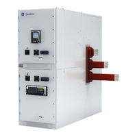
User Manuals: GE SecoGear Metal Clad Switchgear
Manuals and User Guides for GE SecoGear Metal Clad Switchgear. We have
3
GE SecoGear Metal Clad Switchgear manuals available for free PDF download: Application Manual, Installation, Operation And Maintenance Manual, User Manual
GE SecoGear Application Manual (76 pages)
5kv - 15kv IEEE metal-clad switchgear
Brand:
GE
| Category:
Switch
| Size: 2.33 MB
Table of Contents
Table of Contents
3
Section 1. Secogear Switchgear Concepts and Basic Configurations
9
Secogear Metal-Clad Switchgear
9
Figure 1-1: Typical Secogear 2-High Section
9
Figure 1-2: Section Contents
10
Figure 1-3: Typical One-High Breaker
10
Table 1-1: Typical Dimensions for Indoor Construction
10
Switchgear Standards
11
Underwriters Laboratories, Inc. (UL)
11
Service Conditions
11
Temperature
11
Humidity
11
Altitude
11
Applicable Industry Standards
11
Modular Construction and Typical Sectional Views
11
Modular Compartments
11
Figure 1-4: Typical Two-High Breakers
11
Figure 1-5: Dual VT Rollouts, Line/Bus Connected - Upper or Lower Section
12
Figure 1-6: Dual CPT Rollouts, Line/Bus Connected - Upper or Lower Section
12
Figure 1-7: 1200 A/2000 a - Upper or Lower Breaker Section
12
Figure 1-8: VT Rollout, Line/Bus Connected and Fuse Rollout, Line Connected - Lower Section
12
Rollout Configurations
13
Figure 1-9: Dual Rollouts
13
Figure 1-10: Single Rollouts
13
Table 1-4: Permitted Rollout Unit Combinations
13
Two-High Breaker and Auxiliary Stacking
14
Figure 1-11: Breaker in Compartment A, Bus-Connected Vts in Compartment B
14
Figure 1-12: Breaker in Compartment A, Line-Connected Vts in Compartment B
14
Figure 1-13: Breaker in Compartment A, Bus-Connected Vts and CPT Fuse Rollout in Compartment B
14
Figure 1-14: Breaker in Compartment A, Line-Connected CPT and VT Rollouts in Compartment B
14
Figure 1-15: Breaker in Compartment A, Line- and Bus-Connected VT Rollouts in Compartment B
15
Figure 1-16: Breaker in Compartment B, Bus-Connected VT Rollout in Compartment a
15
Figure 1-17: Breaker in Compartment B, Bus-Connected CPT in Compartment a
15
Figure 1-18: Bus Entry in Compartment a - Cabling Above, Breaker in Compartment B - Cabling below
15
Figure 1-19: Breaker in Compartment B, Bus-Connected Vts and CPT in Compartment a
16
Figure 1-20: Breaker in Compartment B, Line-Connected VT Rollouts in Compartment a
16
Figure 1-21: Typical Two-High Breaker Section - Cabling below
16
Figure 1-22: Typical Two-High Breaker Section - Cabling above
16
Figure 1-23: Breaker in Compartment a - Cabling Above, Bus Entry in Compartment B - Cabling below
17
Figure 1-24: Breaker in Compartment A, Bus-Connected Vts and Line-Connected Fuse Rollout in Compartment B
17
Figure 1-25: Bus-Connected Vts in Compartment A, Bus Tie Breaker in Compartment B
17
Figure 1-26: Bus-Connected Vts in Compartment A, Aux Tie in Compartment B
17
Section 2. Circuit Breaker Selection
18
Circuit Breaker Ratings
18
Selection Considerations
18
Circuit Voltage
18
System Frequency
18
Short-Circuit Current
18
Figure 2-1: Secovac VB2+ Circuit Breaker
18
Closing and Latching Current
19
Continuous Current
19
Rated Interrupting Time
19
Duty Cycle
19
Special Switching Applications
19
Automatic Transfer
19
Table 2-1: Secovac VB2+ Vacuum Circuit Breaker Characteristics
19
Capacitor Switching
20
Service Conditions
20
Usual Service Conditions
20
Unusual Service Conditions
20
Abnormal Temperature
20
Temperature Rise
20
High Altitude
20
Table 2-2: Secovac Breaker Capacitor Switching Capabilities
20
Breaker Accessories
21
Breaker Lift Truck
21
Table 2-3: Altitude Correction Factors* for Secovac VB2+ Circuit Breakers and Secogear Switchgear
21
Related Circuit Breaker References
22
Figure 2-2: Lift Truck
22
Figure 2-3: Secovac VB2+ Breaker Front Panel
23
Figure 2-4: Spring Discharge Instructions
23
Typical Breaker Device Internals
24
Figure 2-5: System Wiring Diagram
24
Figure 2-6: Terminal Block Located in Switchgear
24
Figure 2-7: Secondary Disconnect
24
Figure 2-8: Example - Main Breaker Control Circuit, 850 Relay, Expanded MOC Switch
25
Section 3. Control Power Equipment
26
Control Power Requirements
26
Breaker Close and Trip Considerations
26
Breaker Tripping
26
Table 3-1: Secovac VB2+ IEEE Circuit Breaker Control Voltages and Currents
26
Table 3-2: Contact Ratings for MOC, TOC, and Breaker Auxiliary Switches
26
DC Battery Trip
27
Direct Acting Undervoltage Trip Device
27
Secovac Autocharge Capacitor Trip Device
27
Breaker Closing
27
Indicating Lamps
28
Relaying
28
Excitation Power
28
Other Loads
28
Table 3-3: Simultaneous Breaker Tripping
28
Table 3-4: GE Type HEA Lockout Relay Coil Current Characteristics
28
Table 3-5: AC Load Factor for Charger Battery Voltage
28
Control Power Source Selection
29
DC Control Power Equipment
29
Battery Systems
29
Lead-Acid Batteries
29
Nickel-Cadmium Batteries
29
Battery Capacity and Sizing
29
Table 3-6: Battery Selection Guide
29
Battery Chargers
30
Table 3-7: Battery Sizing, Example a
30
Table 3-8: Battery Sizing, Example B
30
AC Control Power Equipment
31
Application
31
Selection
31
Table 3-9: AC Load Estimating Example
31
Guide to Estimating Heat Loss
32
Table 3-10: Heat Loss Per Breaker
32
Table 3-11: Heat Loss Per Section
32
Section 4. System and Equipment Protection
33
Secogear Medium-Voltage Switchgear Application and Technical Guide DET
34
Figure 4-1: Multilin Website Features - Motor Protection Selection
34
Figure 4-2: Multilin Website Features - Digital Metering Selection
35
Basic System Protection
36
Phase Overcurrent Protection
36
Incoming Lines
36
Feeders
36
Feeder Ties
36
Bus Ties
36
Transformers
36
Generators
36
Ground Overcurrent Protection
37
Incoming Lines
37
Feeders
37
Transformers and Generators
38
Directional Phase Overcurrent Protection
38
Directional Ground Overcurrent Protection
38
High Impedance Ground Fault Detection
38
Differential Protection
38
Bus Protection
39
Transformer Protection
39
Motors
39
Transmission Line
39
Generators
39
Open Phase Protection
39
Automatic Reclosing
39
Directional Power, Underfrequency, and Undervoltage Protection
40
Arc Flash Detection
40
Basic Equipment Protection
40
Circuit Breaker Control and Control Power Protection
40
Instrumentation, Current, and Voltage Transformers
41
AM and VM Scales
41
CT and VT Ratios
41
Table 4-1: Remote Control Schemes
41
Table 4-2: Single Ratio Cts
41
Metering and Test Block
42
Control and Transfer Switches
42
Surge Protection
42
ANSI Device Functions and Acronyms
42
Table 4-3: Multiple Ratio Cts
42
Table 4-4: ANSI Device Codes
42
Section 5. Secogear Switchgear Applications
45
Glossary: Basic Equipment Applications
45
General-Purpose Feeders (GPF)
46
Protective Scheme Selection
46
Optional Equipment Selection
46
Protection
46
Current Transformers for Differential Circuits
46
Indication
46
Control
47
Figure 5-1: General-Purpose Feeder
47
Transformer Primary Feeders (TPF)
48
Protective Scheme Selection
48
Optional Equipment Selection
48
Single-Source Incoming Lines (SSIL), or Dual Source with Normally Open Tie Breakers
48
Figure 5-2: Transformer Primary Feeder
48
Optional Equipment Selection
49
Protection
49
Indication
49
Control
50
Figure 5-3: Single-Source Incoming Line
50
Dual-Source Incoming Lines (DSIL)
51
Basic Equipment Selection
51
Optional Equipment Selection
51
Protection
51
Indication
51
Control
51
Location of Optional Devices
51
Bus Ties (BT)
52
Basic Equipment Selection
52
Optional Equipment Selection
52
Protection
52
Figure 5-4: Dual-Source Incoming Line
52
Indication
53
Control
53
Figure 5-5: Bus Tie
53
Bus Entrances (BE)
54
Basic Equipment Selection
54
Optional Indication Selection
54
Induction Motor Feeders (IMF)
54
Protective Scheme Selection
54
Figure 5-6: Bus Entrance
54
Optional Equipment Selection (for IMFE, IMF1, IMF2)
55
Protection
55
Indication
55
Control
55
Location of Optional Devices
55
Figure 5-7: Induction Motor Feeder
56
Reduced Voltage Starting
57
Synchronous Motor Feeders (SMF)
57
Protective Scheme Selection
57
Figure 5-8: Reduced Voltage Reactor Start
57
Optional Equipment Selection (for SMF1 and SMF2)
58
Protection
58
Excitation
58
Indication
58
Control
58
Location of Optional Devices
58
Figure 5-9: Synchronous Motor Feeder
59
Standard Breaker and Auxiliary Configurations
60
Figure 5-10: Sample Lineup - a
60
Figure 5-11: Sample Lineup - B
60
Standard Tie Breaker and Auxiliary Configurations
61
Figure 5-12: Tie Breaker and Aux Tie Stack
61
Figure 5-13: Bus Vts on each Side of Tie Breaker
61
Figure 5-14: Feeder Breakers in Upper Compartment
61
Figure 5-15: Bus VT in the Aux Tie Compartment
61
Figure 5-16: Typical Main-Tie-Main Example with Eight Feeder Breakers
62
Section 6. Standard Secogear Construction, Features, and Installation
63
Documentation
63
Construction
63
Indoor Equipment
63
Hardware
63
Breaker Compartments
63
Figure 6-1: Breaker Compartment
63
Visual Breaker Position Indication
64
Auxiliary Compartments
64
Compartment Doors
64
Figure 6-2: Ground Shoe in Breaker Cell
64
Figure 6-3: Breaker Position - Disconnected (Green)
64
Figure 6-4: Breaker Position - Intermediate (Yellow)
64
Figure 6-5: Breaker Position - Connected (Red)
64
Safety Interlocks
65
Secondary Disconnect Interlocking
65
Figure 6-6: Door Stop and Hinges
65
Figure 6-7: Optional IR Viewing Window
65
Figure 6-8: Optional Lockable T Handle
65
Safety Key Lock Provisions
66
Figure 6-9: Disconnect Plug Not Mechanically Interlocked
66
Figure 6-10: Disconnect Plug Mechanically Interlocked
66
Figure 6-11: Rear Door Padlocking Provision
66
Figure 6-12: Front Door Padlocking Provision
66
Figure 6-13: Breaker Racking Padlock
66
Padlock for Open/Close Pushbutton (Optional)
67
Main Bus
67
Secondary Control
67
Door-Mounted Devices
67
Equipment-Mounted Devices
67
Figure 6-14: Shutter Padlocking Provision
67
Figure 6-15: Open/Close Pushbutton Locked
67
Figure 6-16: Open/Close Pushbutton Open
67
Figure 6-17: CT Mounting in Breaker Compartment
67
Wiring
68
Power Termination Compartment
68
Figure 6-18: Typical Ring-Type Cts Mounted in Secogear Breaker Cell
68
Figure 6-19: Typical Indoor Voltage Transformer
68
Figure 6-20: Rear View of Two High Compartment Showing Cable Trough
68
Ground Bus
69
Equipment Heaters
69
Finish and Paint
69
Unit Nameplates
69
Accessories
69
Breaker Test Box
69
Breaker Racking Mechanism
69
Ground and Test Device
69
Figure 6-21: Cable Trough Opening
69
Figure 6-22: Ground Bus Bar Bolt Locations
69
Identification of Breakers and Equipment
70
Figure 6-25: Ground and Test Device
70
Figure 6-26: Secovac Barcode
70
Figure 6-27: Secovac Nameplate
70
Figure 6-28: Secogear Label
70
Installation Information
71
Shipping Splits
71
Indoor Foundation Preparation
71
Table 6-1: Secogear Characteristics
71
Anchoring Details
72
Embedded Floor Channel Requirements
72
Figure 6-29: Section Cutaway (Height, Width, and Depth)
72
Figure 6-30: Secogear Installation Drawing - Indoor Anchoring Method
72
Figure 6-31: Secogear Primary Indoor Anchoring Method
73
Figure 6-32: Secogear Alternate Indoor Anchoring Method
73
Figure 6-33: Installation Top View
73
Section 7. Ground and Test Device
74
Safety
74
Figure 7-1: Device, Front View
74
Figure 7-2: Device, Contact Arms
74
Table 7-1: Secovac VB2+ Vacuum Circuit Breaker Characteristics
74
Advertisement
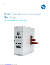
GE SecoGear Installation, Operation And Maintenance Manual (56 pages)
5kV-15kV IEEE Metal-Clad Switchgear
Brand:
GE
| Category:
Protection Device
| Size: 4.68 MB
Table of Contents
Table of Contents
2
1 Introduction
11
Safety
11
Table 1-1: Rated Electrical Characteristics
11
Maintenance
12
2 Receiving, Handling and Storage
13
Receiving
13
Inspecting for Damage
13
Filing a Claim
13
Handling
13
Enclosure Lifting
13
Example
13
Figure 2-1: Recommended Lifting Method (Front View)
13
Forklifts
14
Using Rollers
14
Figure 2-2: Recommended Lifting Method (Side View)
14
Figure 2-3: Corner Warning Label
14
Figure 2-4: Placing Forklift Tines under Equipment Shipping Skid
14
Figure 2-5: Moving Using Rollers
14
Storage
15
Switchgear
15
Secovac Vacuum Circuit Breakers
15
Figure 2-6: Secovac Vacuum Circuit Breakers
15
3 Secogear Construction
16
Circuit Breaker Compartment
16
Closed-Door Drawout
16
Figure 3-1: Section Contents
16
Fixed Primary Disconnect Contacts
17
Figure 3-2: Circuit Breaker Manual Rack In/Out
17
Figure 3-3: Circuit Breaker Automatic Rack In/Out
17
Figure 3-4: Secogear Primary/Secondary Disconnects
17
Figure 3-5: Circuit Breaker Primary/Secondary Cluster
17
Automatic Shutters
18
Interlocks
18
Figure 3-6: Automatic Shutters
18
Figure 3-7: Interlock for Secondary Disconnect Plug Removal
18
Current Transformers
19
Figure 3-8: Open-Close-Open Safety Interlock Plungers
19
Figure 3-9: Padlock for Door and Breaker Rack In/Out
19
Figure 3-10: Current Transformers
19
Auxiliary Compartments
20
Voltage Transformers
20
Control Power Transformers and Fuse Trays
20
Figure 3-11: Voltage Transformers
20
Figure 3-12: Fuses-Only Tray
20
Figure 3-13: CPT with Fuses Tray
20
Manually Operated Ground and Test Device
21
Circuit Breaker
21
Figure 3-14: Manual Ground and Test Device
21
Primary Disconnects
22
Figure 3-15: Secovac Vacuum Circuit Breaker
22
Figure 3-16: Disconnect Finger Cluster
22
Lift Truck
23
Racking Mechanism
23
Remote Racking System (Optional)
23
Figure 3-17: Lift Truck Ready for Use
23
Figure 3-18: Remote Racking Operator
23
Figure 3-19: Remote Switch Operator
23
4 Installation
24
Site Location
24
Foundation Requirements
24
Figure 4-1: Secogear Installation Drawing - Indoor Anchoring Method
24
Assembling Shipping Sections
25
Figure 4-2: Secogear Primary Indoor Anchoring Method
25
Figure 4-3: Lineup Shown Assembled
25
Bolting Sections Together
26
Figure 4-4: Lift Plugs in Position
26
Figure 4-5: Position Wires for Clearance
26
Figure 4-6: Front Bolt Locations (Left and Right)
26
Figure 4-7: Rear Bolt Locations (Left and Right)
26
Attach Trim Covers
27
Wiring
27
Taped Insulation
27
Figure 4-8: Front Left Trim Covers Installed
27
Figure 4-9: End Cover Assembly
27
Figure 4-10: Tape Bus Bars
28
Figure 4-11: Tape Dead-End Bus Joint
28
Part 1: Bus Bars, 5 Kv or 15 Kv
28
Part 2: Taped Joints, 5 Kv or 15 Kv
28
Table 4-1: Tape Bus Bars
28
Table 4-2: Tape Dead-End Bus Joint
28
Figure 4-12: Tape Bus Connection Joint
29
Figure 4-13: Tape Current Transformer Joint
29
Table 4-3: Tape Bus Connection Joint
29
Table 4-4: Tape Current Transformer Joint
29
Figure 4-14: Tape Tee Connection Joint
30
Figure 4-15: Tape Double Bus Bar Joint
30
Table 4-5: Tape Tee Connection Joint
30
Table 4-6: Tape Double Bus Bar Joint
30
Bus Bar Installation
31
Figure 4-16: Bus Access Via Rear Cover Plates
31
Figure 4-17: Bus Access Panels
31
Figure 4-18: Bus Accessible
31
Figure 4-19: Side Bus Shrouds
31
Figure 4-20: Main Bus Connection - Rear View
32
Table 4-7: Main Bus Sizes
32
Table 4-8: Riser/Runback Bus Size
32
Figure 4-21: Main Bus Connection - Plan (Top) View
33
Figure 4-22: Main Bus Connection - through Joint
33
Figure 4-23: Main Bus Connection - Start or End Joint
33
Recommended Torque Values
34
Ground Bus Installation
34
Figure 4-24: Typical Ground Bus
34
Figure 4-25: Ground Bus - Plan View
34
Figure 4-26: Ground Bus - Rear View
34
Table 4-9: Recommended Torque Limits
34
Cable Access Panels
35
Final Inspection
35
Figure 4-27: Upper Cable Plates
35
Figure 4-28: Lower Cable Plates
35
5 Circuit Breaker Installation/Removal
36
Inspection and Preparation
36
Racking
36
Figure 5-1: Two-High Breaker Section
36
Installing Secovac Vacuum Circuit Breaker into Switchgear
37
Compartment
37
Place Circuit Breaker Onto the Lift Truck
37
Figure 5-2: Lowered Lifting Platform
37
Figure 5-3: the Hoist Rail Slots
37
Figure 5-4: Press the Front Pedal to Lock Lift Truck
37
Figure 5-5: Secovac VCB Tab Locked in Lift Truck Slot
37
Figure 5-6: Secovac VCB Properly Mounted on Lift Truck
37
Insert Circuit Breaker into Switchgear Compartment
38
Figure 5-7: Release Floor Lock
38
Figure 5-8: Lift Truck Crank Handle
38
Figure 5-9: Cable Winch Spool
38
Figure 5-10: Cable Secured to Hoist
38
Figure 5-11: Lift Truck Arm (Left) Aligned with Switchgear Guide Slot (Right)
38
Figure 5-12: Lift Truck Guide Arm Stops
38
Figure 5-13: Press the Front Lever to Lock Lift Truck
38
Figure 5-14: Operation Handle
39
Figure 5-15: Operation Handle Fully Engaged into Switchgear Compartment
39
Figure 5-16: Press down on the Interlock Pin and Rotate Clockwise to Lock
39
Figure 5-17: Unlock VCB from Lift Truck
39
Figure 5-18: Lock VCB into Switchgear
39
Figure 5-19: Rotate Interlock Pin Counterclockwise to Unlock the Latch Handle
40
Figure 5-20: Interlock Latch Handle
40
Figure 5-21: Stop in Proper Position
40
Figure 5-22: Eliminating Stop Interference
40
Figure 5-23: Release Floor Lock
40
Removing the Circuit Breaker
41
Racking the Circuit Breaker to Connected Position
41
Figure 5-24: Release Secondary Plug from VCB
41
Figure 5-25: Insert Secondary Plug and Lock into Switchgear
41
Racking the Circuit Breaker to Disconnected/Test Position
42
Figure 5-26: Racking Handle
42
Figure 5-27: Racking Handle Insertion on Door
42
Figure 5-28: Access Hole Open
42
Figure 5-29: Disconnected/Test Position (Green)
42
Figure 5-30: Intermediate Position (Yellow)
42
Figure 5-31: Connected Position (Red)
42
6 Testing and Inspection
43
Circuit Breaker Operation Test
43
Circuit Breaker Test Jumper (Optional)
43
Circuit Breaker Test Box (Optional)
43
Figure 6-1: Secovac Test Box
43
7 Circuit Breaker Operation
44
Closing Operation
44
Opening Operation
44
8 Energizing the Switchgear
45
Before Energizing
45
9 Maintenance
46
Circuit Breaker and Instrument Compartments
46
Circuit Breaker Test for Proper Operation
46
Checks after the Circuit Breaker Is De-Energized
46
Lubrication
47
Instruments, Components and Relays
47
Switchgear Interior
47
Main Bus Compartment
48
Figure 9-1: Rear Compartment Assembly Illustration
48
Replacing Current Transformers (Cts)
49
Wire the Cts
49
Figure 9-2: Cts Mounted in Compartment
49
Figure 9-3: CT Spacers, 7/8" (Left) and 2" (Right)
49
Figure 9-4: CT Spacers Installed
49
Figure 9-5: CT Wire Harness in Compartment
49
Overall Switchgear
50
Padlocks and Keylocks
50
Circuit Breaker Racking Port Padlock Provision
50
Figure 9-6: CT Wires Connected
50
Figure 9-7: CT Installed, Shutters in Open Position
50
Figure 9-8: Secogear Manual Racking Port Padlocked
50
Door Padlock Provision
51
Shutter Padlock Provision
51
Figure 9-9: Compartment Door Padlock
51
Figure 9-10: Shutter Padlock
51
Figure 9-11: Kirk Lock Location in Secogear
51
Key Interlocks (Optional)
52
Kirk Lock
52
Preferred Lock out Tag out Procedure (LOTO)
52
Figure 9-12: Initial Stopper Rod Position
52
Figure 9-13: Locked Stopper Rod Position
52
Paint Refinishing
53
Circuit Breaker Lift Truck
53
10 Repair and Replacement
54
Circuit Breaker Troubleshooting
54
Circuit Breaker Spare Parts
54
Table 10-1: Diagnosis and Troubleshooting Malfunctions
54
11 Notes
55
GE SecoGear User Manual (36 pages)
24kV-27kV Air Insulation Switchgear
Brand:
GE
| Category:
Switch
| Size: 7.04 MB
Table of Contents
Table of Contents
2
General
5
Summary
5
Standard and Specification
5
Operating Conditions
6
Safety and Environment Protection Requirement
6
Handling and Storage
7
Installation of Switchgear
9
Technical Specification
10
Technical Specification for Secogear -Table 1
10
Main Circuit Resistance of Secovac VB2 Plus -Table 3
10
Technical Specification for Secovac VB2 Plus (Circuit Breaker) -Table 2
10
Keylock (Optional)
11
Resistance to Internal Arc Faults (Optional)
11
Technical Specification for Earthing Switch -Table 4
11
Padlock (Optional)
13
Enclosure Design and Equipment
14
Typical Modules (Figures 3/1)
14
Enclosure and Partitioning (Figure 3/2)
14
Switchgear Structure
15
Cable Connections
18
Operations and Trouble Shooting
19
Rack Circuit Breaker out from Service Position to Test / Disconnected Position
20
Circuit Breaker
21
Earthing Switch Operation
21
Interlocking of the Switchgear
22
Debugging of Combined Overcurrent Relay
23
Inspection and Maintenance
24
Summary
24
Inspection and Maintenance Interval
24
Diagnosis and Trouble Shooting for Malfunction During Operations
25
Maintenance Item and Cycle
25
Routine Inspection
25
Service
26
Repairs
27
Inspection Items
27
Performance Test
27
Major Repairs and Examples
28
Inspection and Replacement of the Main Busbar
28
Inspection and Replacement of the Fixed Contact and Spout Bushing
29
Inspection and Replacement of the Shutter Mechanism
30
Replacing the Earthing Switch
30
Replacing the Current Transformer
32
Inspection and Replacement of the Surge Arrester
33
Main Busbar
34
Spare Parts
35
Appendix A - Onsite Service Safety Instruction
35
North America
36
Advertisement
Advertisement
Related Products
GE SE-100E
GE SE-1OOM
GE SE-1OOS
GE SE-100M
GE SE-100S
GE Digital Energy STS-400-25-4
GE S2020
GE S2024G
GE Digital Energy STS-230-40-2-RM
GE Digital Energy STS-230-63-2-RM
GE Categories
Refrigerator
Ranges
Microwave Oven
Air Conditioner
Dishwasher
More GE Manuals
Login
Sign In
OR
Sign in with Facebook
Sign in with Google
Upload manual
Upload from disk
Upload from URL