Sign In
Upload
Manuals
Brands
GE Manuals
Medical Equipment
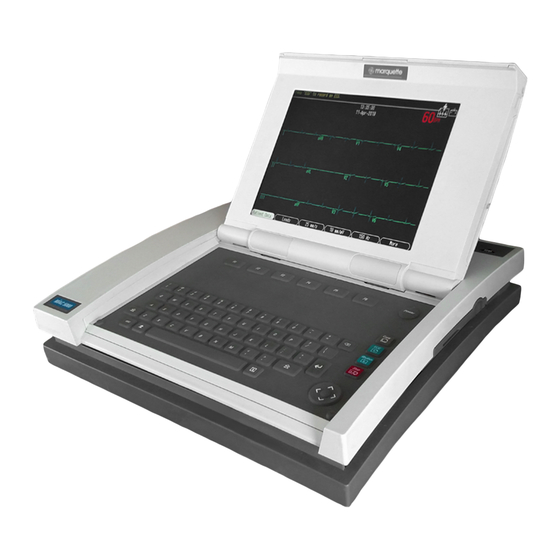
MAC 5000
GE MAC 5000 Manuals
Manuals and User Guides for GE MAC 5000. We have
4
GE MAC 5000 manuals available for free PDF download: Operator's Manual, Service Manual, Field Service Manual
GE MAC 5000 Operator's Manual (258 pages)
Resting ECG Analysis System
Brand:
GE
| Category:
Medical Equipment
| Size: 4.61 MB
Table of Contents
CE Marking Information
3
Compliance
3
Exceptions
3
Table of Contents
5
Introduction
17
Manual Information
19
Purpose
19
Intended Audience
19
Revision History
19
Conventions
19
User Instructions
20
Safety Information
21
Definitions
21
Equipment
21
Legal Notice
23
Responsibility of the Manufacturer
23
General Information
24
Equipment Symbols
27
Service Information
28
Service Requirements
28
Equipment Identification
28
Equipment Overview
29
Equipment Description
31
Front View
31
Internal View
32
Back View
33
Connectors
34
Keyboard
36
Keyboard-Exercise Test Keys (Option)
37
Acquisition Module
38
Getting Started
41
Prepare the Equipment for Use
41
Software Description
47
Selecting Menu Functions
51
Entering Data
54
Preparing the Patient
57
Prepare the Patient's Skin
59
Apply the Electrodes
60
Resting Electrodes
60
Exercise Electrodes (with Exercise-Option)
65
Entering Patient Information
67
Enter Patient Information
69
Preparation
69
Enter the Information
70
Using a Patient Card Reader (Option)
71
Connect the Card Reader
71
Slide Card
71
Receive Orders from a MUSE CV System (Option)
72
Preparation
72
Load the Orders
73
Select the Orders to Receive
73
Select an Order to Complete
74
Complete the Order
74
Enter Orders Manually (Option)
75
Preparation
75
Create an Order
75
Select an Order to Complete
76
Complete the Order
76
Recording an ECG
77
Record a 15 Lead, Resting, Pediatric, or Vector Loops ECG
79
Preparation
79
Record the ECG
79
Record a Signal Averaged ECG (Options)
80
Preparation
80
Record the ECG
80
Record a Master's Step Test (Option)
81
Preparation
81
Enter Patient Data
81
Confirm Test Steps
81
Record the ECG
81
Run the Test
82
Using ACI-TIPI (Option)
83
Preparation
83
Enter the Information
83
Exercise Stress Test (Option)
85
Start an Exercise Stress Test
87
Patient Data
87
Exercise Test Keys
88
Test Phases
89
Pretest Phase
89
Exercise Phase
91
Recovery Phase
93
Test End Phase
94
Edit Protocols Options
97
Overview
99
Operating Steps
100
Variable Protocols
101
Pre-Test Phase Screen
102
Pre-Test Protocol Information
103
Advance to Exercise
104
Advance to Recovery
105
Advance to Test End
106
Save Current Protocol
107
Printing an ECG Report
109
Print Stored ECG Reports
111
Preparation
111
Select the Ecgs
111
Print the Ecgs
111
Transmitting an ECG
113
Transmit Stored Ecgs by Modem (Option)
115
Preparation
115
Select the Receiving Device
116
Select the Ecgs
116
Transmit the Ecgs
116
Transmit Stored Ecgs Locally
117
Preparation
117
Select the Method of Transmission
118
Select the Ecgs
118
Transmit the Ecgs
118
Transmit Stored Ecgs by Wireless (Option)
119
Preparation
119
Select the Receiving Device
120
Select the Ecgs
120
Transmit the Ecgs
120
Receiving an ECG
121
Receive Ecgs by Modem (Option)
123
Preparation
123
Receive the Ecgs
124
Receive Ecgs Locally
125
Preparation
125
Receive the Ecgs
126
Retrieve Confirmed Ecgs from a MUSE CV System Via Modem (Option)
127
Preparation
127
Select a MUSE CV System
128
Select an ECG
129
Display or Print the ECG
129
Retrieve Confirmed Ecgs from a MUSE CV System Via Wireless (Option)
130
Preparation
130
Select a MUSE CV System
131
Select an ECG
131
Display or Print the ECG
132
Editing an ECG
133
Edit Demographic and Interpretive Data
135
Preparation
135
Select the Ecgs
135
Edit Demographic Data
136
Edit Interpretive Data
136
Store the Edited ECG
139
Deleting an ECG
141
Delete Stored Ecgs
143
Preparation
143
Select the Ecgs
143
Delete the Ecgs
144
Delete Stored ECG Orders (Option)
145
Preparation
145
Select the Orders
145
Delete the Orders
146
Completing Other Tasks
147
Prepare a Disk for Use
149
Lock and Unlock
149
Format
149
Eject a Disk from the Drive Slot
150
Display Stored Ecgs
151
Preparation
151
Select the Ecgs
151
Display the Ecgs
152
Defining the System Setup
153
To Use the System Setup Function
155
Select the System Setup Function
155
Define the System Parameters
156
Save Your Changes
156
Program the System to Automatically Do a Task
157
To Power up the System into a Specific Resting Function
157
To Preview ECG Data before Analysis
157
To Print a Resting ECG Report
158
To Print a Signal Averaged ECG Report
158
To Store an ECG
159
To Transmit an ECG
159
Enable or Disable the ACI-TIPI Option
160
Define the Basic System Setup
161
Miscellaneous Setup
161
Patient Questions
162
Screen Colors
164
Transmission
165
Date and Time
166
Language
166
Power up Options
167
Order Manager Interface
167
PS/2 Port
168
Define the ECG Setup
169
ECG Acquisition/Analysis
169
Patient Questions
171
Writer Setup
171
Resting, Pediatric, 15 Lead, and Vector Loops ECG Reports
172
Analog Outputs
175
Define the Exercise Test Setup (Option)
176
Miscellaneous Setup
176
Patient Data/Questions
176
Writer Setup
177
12 And 15 Lead Exercise Reports
178
Final Report
180
Screen
181
Inputs / Outputs
181
Define the Signal Averaged ECG Setup (Option)
183
Master's Step Setup (Option)
184
Miscellaneous Setup
185
Print Setup
185
Save Setup
185
Restore Setup
185
Appendix A - Maintenance
187
General
189
Inspecting and Cleaning
190
Precautions
190
Visual Inspection
190
Cleaning
191
Changing the Paper Tray Size
192
To Change to A4 Paper Size
192
To Change to Standard Paper Size
192
Replacing Paper
193
Storing Paper
194
Thermal Paper
194
Archivist Paper
195
Maintaining the Battery
196
Battery Gauge Icon
196
Charging the Battery
196
Periodic Maintenance
198
Replacing the Battery
198
Mounting or Dismounting the Trolley
200
Mount the System Onto the Trolley
200
Dismount the System from the Trolley
201
Replacing Acquisition Module Leadwire Adapters
202
Handling a Disk
203
Appendix B - Troubleshooting
205
Introduction
207
First Things to Ask
207
Visual Inspection
207
Equipment Problems
208
Reducing ECG Data Noise
208
There Is no ACI-TIPI Report
208
No BP Readings from External Device
209
Treadmill / Ergometer Does Not Move
209
System Errors
210
Appendix C - Editing Acronyms
211
Resting ECG Acronyms
213
Appendix D - Technical Specifications
219
Computerized Electrocardiograph
221
Electrical
223
Physical
224
Safety
225
Environmental
227
Battery
228
Writer
229
Vectorcardiography
230
Pediatric Analysis
231
Late Potential Analysis
232
(Hi-Res and Phi-Res Signal Averaged Electrocardiography
232
Appendix E - Report Formats
233
Format Description
235
By 2.5S + 1 Rhythm Lead Format
235
Key to Bottom of Exercise Reports
236
Additional Report Names
237
In-Test Reports
239
Exercise Final Report Names
240
Appendix F - Master's Step Data
241
Master's Step Table
243
ST-T Change
245
Positive
245
Borderline
245
Negative
245
Advertisement
GE MAC 5000 Operator's Manual (229 pages)
resting ecg analysis system
Brand:
GE
| Category:
Medical Equipment
| Size: 5.58 MB
Table of Contents
Marking Information
3
Table of Contents
5
Introduction
9
1 Introduction Manual Information
11
Intended Audience
11
Purpose
11
Conventions
12
Styles
12
Symbol
12
User Instructions
13
Definitions
14
Equipment
14
Safety Information
14
Caution
15
Warning
15
General Information
17
Intended Use
17
Recording Ecgs During Defibrillation
19
Accuracy of the Input Signal Reproduction
20
Installation and Connection
20
Modulating Effects in Digital Systems
20
Parts and Accessories
21
Equipment Symbols
22
Service Information
23
Service Requirements
23
Equipment Identification
24
Equipment Overview
25
Front View
27
2 Equipment Overview Equipment Description
27
Internal View
28
Back View
29
Back Panel
30
Connectors
30
Keypad
31
Acquisition Module
33
Lead Labels
34
Leadwire Adapters
35
Getting Started
36
Mount the System to the Trolley (Option)
36
Prepare the Equipment for Use
36
Mount the Modem to the Trolley (Option)
38
Mount the Card Reader (Option–Japan Only)
39
Mount the Articulating Arm (Japan Only)
40
Connect the Acquisition Module Cables
41
Connect the System Cables
41
Verify Correct Operation
42
Software Description
43
Start up Screen
43
Main Menu
44
Main Menu Functions
45
Pressing a Function Key
47
Selecting Menu Functions
47
Using the Arrow Pad
47
Entering Data
49
Type Data into a Highlighted Field
49
Selecting Items from a List
50
3 Preparing the Patient
53
Prepare the Patient’s Skin
55
Apply the Electrodes
56
Standard 12 Lead Placement
56
Standard 15 Lead Placement
57
Frank X,Y,Z Placement
58
NEHB Placement
59
Pediatric Placement
60
4 Entering Patient Information
61
Enter the Information
63
Preparation
63
Connect the Card Reader
65
Slide Card
65
Using a Patient Card Reader (Option–Japan Only)
65
Receive Orders from a MUSE CV System (Option)
66
Load the Orders
67
Select an Order to Complete
67
Select the Orders to Receive
67
Complete the Order
68
Enter Orders Manually (Option)
69
5 Recording an ECG
71
Record a 15 Lead, Resting, Pediatric, or Vector Loops ECG
73
To Transmit the ECG
74
Record a Signal Averaged ECG (Options)
75
To Average the ECG Data
76
To Store the ECG
76
Record a Master’s Step Test (Option–Japan Only)
77
Connect Masters’ Step
77
Enter Patient Data
78
Confirm Test Steps
78
Record the ECG
78
Run the Test
78
To Store the Test
79
Using ACI-TIPI (Option)
80
6 Printing an ECG Report
83
Print Stored ECG Reports
85
Print Ecgs from a Different Disk?
86
7 Transmitting an ECG
87
Transmit Stored Ecgs by Modem (Option)
89
Select the Receiving Device
90
Select the Ecgs
90
Transmit the Ecgs
90
Transmit Stored Ecgs Locally
91
Select the Method of Transmission
92
8 Receiving an ECG
93
Receive Ecgs by Modem (Option)
95
Receiving an ECG Receive Ecgs by Modem (Option)
95
Receive Ecgs Locally
97
Receive the Ecgs
98
Retrieve Confirmed Ecgs from a MUSE CV System (Option)
99
Select a MUSE CV System
100
Display or Print the ECG
102
9 Editing an ECG
103
Edit Demographic and Interpretive Data
105
Edit Demographic Data
106
Edit Interpretive Data
106
Edit Resting, Pediatric, or Vector Loops Measurements
107
Edit Signal Averaged ECG Measurements
107
Edit Diagnostic Statements
108
To Insert or Append Free Text
108
To Move a Statement to a New Line
109
To Delete a Statement
109
To Join Two Statements
109
Store the Edited ECG
109
10 Deleting an ECG
111
Delete Stored Ecgs
113
Deleting an ECG Delete Stored Ecgs
113
Delete Stored ECG Orders (Option)
115
Delete the Orders
116
11 Completing Other Tasks
117
Prepare a Disk for Use
119
Lock and Unlock
119
Format
119
Eject a Disk from the Drive Slot
120
Display Stored Ecgs
121
Display the Ecgs
122
To Display Ecgs from a Different Disk
123
12 Defining the System Setup
125
To Use the System Setup Function
127
Enter the System Setup Password
127
Define the System Parameters
127
Save Your Changes
128
Program the System to Automatically Do a Task
129
To Power up the System into a Specific Resting Function
129
To Preview ECG Data before Analysis
129
To Print a Resting ECG Report
130
To Print a Signal Averaged ECG Report
130
To Store an ECG
131
To Transmit an ECG
131
Enable or Disable the ACI-TIPI Option
132
Define the Basic System Setup
133
Miscellaneous Setup
133
Patient Questions
136
Screen Colors
139
Transmission
140
Date and Time
142
Language
143
Power up Options
143
Order Manager Enable
144
PS/2 Port
144
Define the ECG Setup
145
ECG Acquisition/Analysis
145
Writer Setup
149
Resting, Pediatric, 15 Lead, and Vector Loops ECG Reports
150
Confirmed Reports
152
Unconfirmed Reports
153
Extra Leads (15 Lead ECG Option Only)
154
Vector Loops (Vector Loops Option Only)
154
Analog Outputs
155
Define the Signal Averaged ECG Setup (Option)
156
Master’s Step Setup (Option–Japan Only)
158
Print Setup
159
Save Setup
159
Restore Setup
159
Miscellaneous Setup
159
Maintenance
161
Maintenance General
163
Inspecting and Cleaning
164
Visual Inspection
164
Cleaning
165
Exterior Surfaces
165
Disk Drive
165
Changing the Paper Tray Size
166
To Change to A4 Paper Size
166
To Change to Standard Paper Size
166
Replacing Paper
167
Storing Paper
168
Thermal Paper
168
Archivist Paper
170
Maintaining the Battery
171
Battery Gauge Icon
171
Charging the Battery
171
To Fully Charge the Battery
171
Is the Battery Charging?
172
Periodic Maintenance
173
Replacing the Battery
173
Mounting or Dismounting the Trolley
175
Mount the System Onto the Trolley
175
Dismount the System from the Trolley
176
Replacing Acquisition Module Leadwire Adapters
178
Handling a Disk
179
Updating Software
180
Troubleshooting
181
First Things to Ask
183
Troubleshooting Introduction
183
Equipment Problems
184
Reducing ECG Data Noise
184
There Is no ACI-TIPI Report
184
System Errors
185
Editing Acronyms
187
Resting ECG Acronyms
189
Editing Acronyms Resting ECG Acronyms
196
Technical Specifications
197
Computerized Electrocardiograph
199
Report Formats
207
Format Description
209
Report Formatss Formats Description
210
Additional Report Names
211
F Masters' Step Data
213
Masters' Step Table
215
ST-T Change
218
Calculation
218
Index
219
GE MAC 5000 Service Manual (176 pages)
Resting ECG Analysis System
Brand:
GE
| Category:
Medical Equipment
| Size: 4.92 MB
Table of Contents
Table of Contents
3
1 Introduction
9
Manual Information
11
Revision History
11
Manual Purpose
11
Intended Audience
11
Warnings, Cautions, and Notes
12
Safety Messages
13
Responsibility of the Manufacturer
13
General
14
Equipment Symbols
15
Service Information
17
Service Requirements
17
Equipment Identification
17
Format a
18
Format B
19
Format C
19
2 Equipment Overview
21
General Description
23
Front View
23
Back View
23
Connector Identification
24
Detailed Description
25
Block Diagram
25
Theory of Operation
26
Overview / Block Diagram
26
Power Supplies
29
+3V-Emi
29
Ref2V5
30
Vana+, Vana
31
Clocks
31
Super I/O and FPGA
31
Cpu Atmel At91Rm9200
31
CPU (Stooges)
32
Rtc
32
Cpu
32
External Bus Interface
32
Boot Loader
33
FPGA Internal Logic
34
Board ID Register
35
Xbus Controller
35
Video Interface
35
Interrupt Controller
41
System Interrupt Timer
42
Acquisition Module Interface
42
Thermal Printhead Interface
43
Serial EEPROM Interface
44
Bbus Interface
44
PWM Analog Outputs
44
Beep Generator
45
PC Card Logic
45
Sdram
45
NAND Flash
46
Secure Digital Card Interface
46
Serial EEPROM
46
Daughter Board Interface
46
VGA LCD/CRT Interface
47
LCD Panel EMI Reduction Components
47
CRT Video DAC / Sync / Buffers
47
Acquisition Module Transceiver / Power Switch
48
Transceiver
48
Acquisition Power Regulator / Switch
48
COMM Port Power Switch / Current Limiter / KISS Power
48
Thermal Printhead Power / Pixel Test Hardware
49
Super I/O Peripheral Controller
49
Floppy Drive Support
49
Serial Ports (One Dual Mode RS-232 / Irda)
50
Clock/Calendar
50
PS2 Keyboard Port
50
The Three Stooges
50
Startup Self Identification
51
Bbus
51
Shemp
51
Larry
52
Moe
53
3 Installation
59
Preparation for Use
61
General
61
Trolley Height Adjustment
62
Installing the MAC 5000
64
Installing the External Modem Kit
66
Magnetic Card Reader Installation
68
Bar Code Reader Installation
70
Type-S Trolley Assembly
72
MAC 5000 ST Requirements and Configuration
73
Compatible Blood Pressure Units
73
Compatible GE Medical Systems Information Technologies Treadmills
74
Analog Treadmills
74
Bicycle Ergometers
75
4 Maintenance
77
Introduction
79
Recommended Maintenance
79
Required Tools and Supplies
79
Inspection and Cleaning
80
Visual Inspection
80
Exterior Cleaning
80
Interior Cleaning
80
General
80
Thermal Printhead
81
Battery and Patient Cable Replacement
82
Battery Replacement
82
Patient Cable Replacement
82
Disassembly Guidelines
83
Preliminary Steps
83
Trolley Disassembly
83
Type-S Trolley Disassembly
84
Power Supply
84
Removal
84
Reassembly
85
Top Cover
86
Removal
86
Reassembly
87
Display/Keyboard Assembly
88
Removal
88
Display/Keyboard Reassembly
89
Reassembly
89
Main CPU Board
90
Removal of CPU Board
90
Reassembly of CPU Board
90
Software
92
Service Only Setups
94
Restore System Setups
94
Restore Options
95
Printhead Replacement
96
Removal
96
Reassembly
96
Diskette Drive Removal/Replacement
96
Writer Roller/Carriage Assembly
97
Removal
97
Reassembly
97
Trolley Casters
98
Domestic Electrical Safety Tests
100
AC Line Voltage Test
100
Leakage Tests
101
5 Troubleshooting
103
Assembly Descriptions
105
Introduction
105
Assembly Block Diagram
105
General Fault Isolation
106
Power-Up Self-Test
106
Power-Up Flow Chart
107
Poor Quality Ecgs
107
Visual Inspection
108
Diagnostic Tests
109
Introduction
109
Loading the System Diagnostics
109
Substitute Master Password
109
System Diagnostics Main Menu
110
Display Tests
110
Pixel Verification Test
110
Grey Scale Test Patterns
110
Speaker Test
111
Keyboard Test
111
Writer Tests
112
Battery Tests
114
Battery Status
114
Battery Discharge Test
114
Battery Charge Test
116
Print Charge/Discharge Test Results
116
Communication Tests
116
COM Port Loopback Test
116
External Modem Test
117
Internal Modem Test
117
Ethernet Module Test
117
Acquisition Module Test
117
Analog I/O Tests
117
Analog Output Test
117
Analog Input Test
118
Dcout Loopback Test
118
Ecgout/Qrstrigger Loopback Test
118
Floppy Drive Tests
118
Diskette Format Failure
118
Internal Memory Tests
119
SD Card Tests
119
Equipment Problems
120
ECG Data Noise
120
Missing ACI-TIPI Report
120
No BP from External Device
120
Treadmill/Ergometer Does Not Move
120
System Errors
121
Frequently Asked Questions
122
Maintenance
122
Save Setups
122
Storing Ecgs
122
Format a Disk
122
Cleaning
122
Battery Capacity
123
System Setup
123
Location Number
123
Patient Questions
123
Passwords
124
Clinical
124
Report Format
124
Hi-Res and Phi-Res
124
Editing
124
Entering Patient Data
125
Transmission
125
Losing Fields When Transmitting
125
Input and Output Connectors
126
A Pins (J1)
126
COM1 (COM3/4) Pins (J3)
126
COM2 Pins (J5)
127
Analog Pins (J6)
127
EXT. VID. Pins (J7)
128
CPU PCB Input/Output Signals
129
Battery Pack/Monitor, J2
129
LCD Backlight, J4
129
Keyboard, J8
129
Lcd, J10
130
Power Supply/Motor, J11
131
Thermal Printer, J12
132
Floppy Disk Drive, J13
133
Acquisition Module, J14
134
6 Parts List
135
Ordering Parts
137
General Information
137
Field Replaceable Units
138
Appendix A - Abbreviations
143
Appendix B - Technical Specifications
157
Display
157
Computerized Electrocardiograph
157
Writer
158
Keyboard
158
Electrical
158
Vectorcardiography
158
Hi-Res and Phi-Res Signal-Averaged Electrocardiography
159
Physical
159
Environmental
159
Safety
161
Appendix C - Electromagnetic Compatibility
163
Electromagnetic Compatibility (EMC
165
Guidance and Manufacturer's Declaration - Electromagnetic Emissions
165
Guidance and Manufacturer's Declaration - Electromagnetic Immunity
166
Recommended Separation Distances
168
Compliant Cables and Accessories
169
Advertisement
GE MAC 5000 Field Service Manual (160 pages)
resting ECG analysis system
Brand:
GE
| Category:
Medical Equipment
| Size: 10.16 MB
Table of Contents
Table of Contents
5
Introduction
11
Manual Information
13
Revision History
13
Manual Purpose
13
Intended Audience
13
Conventions
14
Safety Information
15
Definitions
15
Messages
15
Responsibility of the Manufacturer
16
General
16
Equipment Symbols
17
Service Information
18
Service Requirements
18
Equipment Identification
18
Equipment Overview
19
General Description
21
Front View
21
Back View
21
Internal View
22
Preparation for Use
23
Trolley Assembly
23
Connector Identification
24
Paper Installation
25
Controls and Indicators
26
Maintenance
27
Introduction
29
Recommended Maintenance
29
Preventive Maintenance Inspection Report
29
Required Tools and Supplies
29
Inspection and Cleaning
30
Visual Inspection
30
Exterior Cleaning
30
Interior Cleaning
30
General
30
Thermal Printhead
31
Battery and Patient Cable Replacement
32
Battery Replacement
32
Patient Cable Replacement
32
Disassembly Guidelines
33
Preliminary Steps
33
Power Supply
33
Removal
33
Reassembly
34
Top Cover
34
Removal
34
Reassembly
35
Display/Keyboard Assembly
35
Removal
35
Reassembly
37
Main PCB
37
Removal
37
Printhead Replacement
37
Diskette Drive Removal/Replacement
38
Writer Roller/Carriage Assembly
38
Removal
38
Reassembly
38
Domestic Electrical Safety Tests
39
AC Line Voltage Test
39
120 VAC, 50/60 Hz
39
Leakage Tests
40
Leakage Test Diagrams
41
Test #1
41
Test #2
41
Test #3
42
Test #4
42
Ground Continuity
43
Preventive Maintenance
44
Troubleshooting
45
Assembly Descriptions
47
Introduction
47
Assembly Block Diagram
47
Input and Output Connectors
48
A Pins (J1)
48
COM1 (COM3/4) Pins (J3)
48
COM2 Pins (J5)
48
ANALOG Pins (J6)
49
EXT. VID. Pins (J7)
49
Internal Cabling
50
CPU PCB Input/Output Signals
52
Battery Pack/Monitor (J2)
52
LCD Backlight (J4)
52
Keyboard (J8)
53
Lcd (J10)
54
Power Supply/Motor (J11)
55
Thermal Printer (J12)
56
Floppy Disk Drive (J13)
57
Acquisition Module (J14)
57
General Fault Isolation
58
Visual Inspection
58
Power-Up Self-Test
58
Power-Up Flow Chart
59
Poor Quality Ecgs
59
Diagnostic Tests
60
Introduction
60
Loading the System Diagnostics
60
System Diagnostics Main Menu
61
Display Tests
61
Pixel Verification Test
61
Grey Scale Test Patterns
61
Anti-Aliasing Test Pattern
62
Speaker Test
62
Keyboard Test
62
Writer Tests
63
C-Scan Test 2
63
C-Scan Test 3
63
25 MM/S Test Pattern I
63
Roller Test
64
Test Pattern II
64
Test Pattern II Continuous
64
Continuously Run out Paper
64
Battery Tests
64
Battery Status
64
Battery Discharge Test
65
Battery Charge Test
65
Print Discharge Test Results Print Charge Test Results
65
Communication Tests
65
COM Port Loopback Test
65
Modem Test
66
Acq. Module Tests
66
Analog I/O Tests
66
Analog Output Test
66
Analog Input Test
66
Dcout Loopback Test
66
Floppy Drive Tests
66
CPU Theory of Operation
67
General Description
69
Block Diagram
70
Theory of Operation
72
Clocks
72
Cpu
72
Fpga
72
Bootstrap Instruction Unpacker
73
EDO DRAM Controller
73
Xbus Controller
73
LCD Controller VLB Bus Cycle Interface
73
Video Waveform Scrolling
74
Interrupt Controller
75
System Interrupt Generator
75
Acquisition Module Interface
75
Thermal Printhead Interface
76
Serial EEPROM Interface
76
Bbus Interface
76
Uarts
77
PWM Analog Outputs
77
Beep Generator
77
Dram
78
Smartmedia Card
78
Serial EEPROM
78
VGA LCD/CRT Interface
78
Acquisition Module Transceiver/Power Switch
78
Thermal Printhead Power/Pixel Test Logic
78
Superio Peripheral Controller
79
Floppy Drive Support
79
Four RS-232 Serial Ports (One Dual Mode RS-232/Irda)
79
Clock/Calendar
79
External PS-2 Keyboard Port
79
General Purpose Parallel I/O Lines
79
The Four Stooges
79
Startup Self Identification
80
Bbus
80
Curly
80
Shemp
80
Larry
81
Moe
81
Moe
84
Untested "Nominal" Operating Time Specs
85
Parts Lists and Drawings
87
Ordering Parts
89
Introduction
89
Field Replaceable Units
90
MAC 5000Rev B Generic Assembly
91
Generic Assembly
91
Power Supply Assembly
102
Power Supply Assembly
104
Display Assembly
106
Trolley
110
PCB Assemblies
113
801212-003A
115
CPU PCB Assembly
115
Sd801212-003A Cpu
122
Battery Transition PCB
138
SD801220-001A Battery Transition
139
801222-001A
140
Led Pcb
140
Sd801222-001A Led
141
Motor Protect PCB
143
Advertisement
Related Products
GE MAC 800
GE MAC 2000
GE MAC 1600
GE MAC 5500
GE MAC 5500 HD
GE MAC 3500
GE MAC 600 SPY
GE MAC 1200
GE MAC 1200 ST
GE marquette MAC 1100
GE Categories
Refrigerator
Ranges
Microwave Oven
Air Conditioner
Dishwasher
More GE Manuals
Login
Sign In
OR
Sign in with Facebook
Sign in with Google
Upload manual
Upload from disk
Upload from URL