Sign In
Upload
Manuals
Brands
GE Manuals
Medical Equipment
Logiq 500
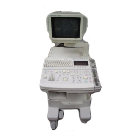
GE Logiq 500 Ultrasound Machine Manuals
Manuals and User Guides for GE Logiq 500 Ultrasound Machine. We have
4
GE Logiq 500 Ultrasound Machine manuals available for free PDF download: User Manual, Advanced Reference Manual, Service Manual, Unpacking Instructions Manual
GE Logiq 500 User Manual (579 pages)
Brand:
GE
| Category:
Medical Equipment
| Size: 5.51 MB
Table of Contents
LOGIQ 500 Basic Users Manual 2233658–100 Rev
4
Table of Contents
7
Chapter 1 -Introduction
19
System Overview
19
Attention
19
Documentation
19
Physical Principle Used
20
General Indications for Use
21
Contraindications
22
Prescription Device
22
Who to Contact
23
Contacting GE Medical Systems-Ultrasound
23
Manufacturer
26
How this Book Is Organized
27
Manual Content
27
Manual Format
29
Chapter 2 -Safety
30
Safety Precautions
30
Precaution Levels
30
Hazard Symbols
31
Patient Safety
32
Equipment and Personnel Safety
34
Device Labels
36
Acoustic Output
44
Warning Label Locations
46
Chapter 3 -Preparing the System for Use
53
Site Requirements
53
Introduction
53
Before the System Arrives
54
Environmental Requirements
55
Console Overview
56
Console Graphics
56
Peripheral/Accessory Connection
59
System Positioning/Transporting
62
Moving the System
62
Transporting the System
65
Wheels
66
Powering on the System
67
Connecting and Using the System
67
Adjusting the Display Monitor
75
Rotate, Tilt, Raise and Lower the Monitor
75
Brightness and Contrast
76
Speakers
79
Probes
80
Introduction
80
Connecting the Probe
80
Cable Handling
82
Activating the Probe
82
Deactivating the Probe
83
Disconnecting the Probe
84
Transporting Probes
84
Storing the Probe
84
Operator Controls
85
Control Panel Map
85
Key Illumination
86
Keyboard
87
Soft Menu Control Panel
88
Mode, Display and Record
91
Measurement and Annotation
93
VCR Controls
95
Beginning an Exam
96
Introduction
96
Beginning a New Patient
97
ID/Name
99
Chapter 4 -Preparing for an Exam
96
Exam Application Preset Selection
101
Introduction
101
Selecting a Probe
101
Chapter 5 -Modes
103
B-Mode
103
Introduction
103
B-Mode Key Operation
103
Reading the B-Mode Display
104
Optimizing the Image
110
Adding Color
126
Gray Scale Color
126
Color Flow Mode
126
Activating Color Flow
127
Reading the Color Flow Display
128
Optimizing the Color Flow Image
129
Power Doppler Imaging (Option)
143
Doppler
144
Introduction
144
Pulsed Wave Doppler
145
Continuous Wave Doppler
147
Reading the Doppler Display
148
Activating Doppler Mode
150
Doppler Optimization
151
M-Mode
165
Introduction
165
Reading the M-Mode or Doppler Spectrum Only Display
165
Reading the Dual Doppler Spectrum Only Display
166
Optimizing the Timeline
167
3Dview Mode (Option)
173
Overview
173
Surface Mode (Option)
174
Overview
174
Mixed Mode Display Formats
175
Display Formats
175
Chapter 6 -Scanning/Display Functions
180
Zooming an Image
180
Introduction
180
Zoom Methods
180
Zooming an M-Mode Image
182
Multi-Image Zoom
183
Freezing an Image
184
Introduction
184
Freezing an Image (Freeze Key)
185
Freezing an Image (Foot Switch Option)
185
Using Cine
186
Introduction
186
Accessing Cine
188
Using Cine Loop
189
Cine Loop Speed
191
Multipl CINE
191
Side Change
192
CINE Gauge
192
CINE Capture (Option-Color Images Only)
192
Capture Frame (Option-Color Images Only)
193
Exiting Cine
193
Helpful Hints
193
Ecg/Cine Gauge/Image Tracking
193
Annotating an Image
194
Introduction
194
Annotation Library
197
Adding Comments to an Image
199
Special Annotation Keys
200
Editing Annotations
201
Body Patterns
202
Introduction
207
Overview
207
Measurement Controls
208
Cursors
209
General Mode Measurements Method
209
Measurement Key
210
General Instructions
211
Erasing Measurements
211
Chapter 7 -General Measurements and Calculations
207
Mode Measurements
212
B-Mode Measurements
212
CFM B-Mode Measurements
217
Doppler Mode Measurements
219
M-Mode Measurements
224
Chapter 8 -Abdomen and Small Parts
228
General Calculations
228
Overview
228
Volume
228
Angle
229
Stenosis Ratio (% Stenosis)
229
S/D Ratio, RI, A/B Ratio or PI
229
Heart Rate
229
Trace Auto
229
Transf Calcs
229
Max PG
229
Mean PG
229
Cardiac Output (CO)
230
Stroke Volume Ratio (SV)
231
Heart Rate (HR)
232
Flow Volume (FV)
233
Trace Auto
234
Flow Volume Output (FVO)
234
Helpful Hints
234
Hip Dysplasia Measurement
235
General Calculation Formulas
237
Chapter 9 -OB/GYN (Basic ob Software Option)
239
Exam Preparation
239
Overview
239
Fetal Doppler
240
Doppler Mode for Fetal Exams
240
Acoustic Output
241
Considerations
241
OB Measurements and Formulas
242
Introduction
242
OB Format Selection
242
OB Measurement Soft Menus and Formulas
243
Helpful Hints
259
OB Summary Reports
260
Starting an Exam
260
OB Report Page Layout
261
Editing the Report
268
Recording Summary Reports
270
Anatomical Survey
271
Overview
271
Editing
272
User Programmed Features
272
OB Graphs
273
Overview
273
OB Graph Selection
274
Advanced Obstetrical Options
276
Options
276
GYN Measurements
277
B-Mode
277
Doppler Mode
278
GYN Summary Report
280
GYN Report Layout
280
GYN Calculation Formulas
281
Chapter 10 -Cardiology (Software Option)
282
Introduction
282
Overview
282
Report Pages
284
BSA Calculation Methods
285
Heart Rate (HR)
285
LV Measurement Methods
286
Cubed Method
286
Teichholz Method
288
Bullet Method
290
Modified Simpson's Rule Method
292
Single Plane Ellipsoid Method
294
Bi Plane Ellipsoid Methods
296
Additional Cardiology Calculations
298
Volume
298
Angle
301
Stenosis (Stenosis Ratio)
302
PHT (Pressure Half Time)
303
MVA (Mitral Valve Area)
303
ET (Ejection Time)
304
Max PG
305
Mean PG
306
Trace Auto
307
S/D (D/S) Ratio, RI, A/B Ratio or PI
308
Heart Rate (HR)
309
Transf Calcs
309
ECG Option
310
Overview
310
Physio Sweep Speed
311
ECG Sub-Menu
311
ECG Lead Placement
312
ECG Sync Mark Display
312
ECG Sub-Menu
313
ECG Gain Pages 2 and 3
315
Ecg/Cine Gauge/Image Tracking
315
Advanced Cardiac Calculations (AMCAL Option)
316
Overview
316
Exam Preparation
318
Introduction
318
General Guidelines
318
Chapter 11 -Vascular (Software Option)
318
Measurements
319
Carotid Artery Measurements
319
Heart Rate (HR)
321
Trace Auto
321
Transf Calcs
321
Vascular Summary Report
322
Introduction
322
Displaying the Summary Report
322
Editing the Summary Report
323
Recording Summary Reports
324
Vascular Calculation Formulas
325
Advanced Vascular (Software Option)
326
Overview
326
Menu Selections
326
Chapter 12-Urology
327
Urology Basic Calculations
327
Overview
327
Presumed Circle Area Ratio (PCAR)
328
Stepper Volume (STVOL)
328
Chapter 13-Recording Images
330
Recording Images
330
Image Memory
330
Recall
332
Helpful Hints
332
Peripheral Devices
333
Video Signal Specifications
350
Maintenance
350
MOD Image Archive (Option)
351
Advanced Recording Option (Software Option)
363
Dicom
363
Chapter 14 -Customizing Your System
365
Time Adjustment
365
Overview
365
Preset Parameters
367
Overview
367
Custom Display
369
Overview
369
Parameter Menu Command Lines
370
Changing a Parameter Value
372
Custom Display Contents
374
Imaging Parameter 1 - Probe Dependent 1)
375
Imaging Parameter 2 - Probe Dependent 2)
377
Imaging Parameter 3 - Probe Dependent 3)
380
Imaging Parameter 4 - Probe Dependent 4)
382
Imaging Parameter 5 - Probe Dependent 5)
384
Imaging Parameter 6 - Probe Dependent 6)
385
Imaging Parameter 7 - Probe Dependent 7)
387
Imaging Parameter 8 - Probe Dependent 8)
388
Imaging Parameter 9 - Probe Dependent 9)
391
Imaging Parameter 10)
392
Imaging Parameter 11)
394
Imaging Parameter 12)
396
Imaging Parameter 13)
398
Imaging Parameter 14)
401
Imaging Parameter 15)
402
Imaging Parameter 16)
404
Imaging Parameter 17)
405
Imaging Parameter 18)
407
System Parameters
409
Overview
409
System Parameters Contents
410
System Setup)
411
System Setup)
413
System Setup)
416
System Setup - Body Pattern)
417
System Setup - Recording)
421
System Setup - User ID and Password)
423
Dicom)
425
Preset Program
426
Overview
426
Preset Program Contents
427
Application)
428
Application)
429
Application - Measurement)
430
Application - Measurement)
433
Application - Measurement Sub-Menu)
435
Page 5 & 6 of 10 (Application – Measurement Sub-Menu)
435
Application - Annotation Library)
451
Application - Patient Information)
451
Page 8 & 9 of 10 (Application – Annotation Library)
451
Save Values
452
Overview
452
Saving Scan Values
452
Exam Applications Presets
454
Overview
454
Defining a User Preset
454
Naming a User Preset
457
Deleting User Presets and Names
458
Recall Preset
458
User Define Function
459
Overview
459
Programming the User Define Function
459
User Define Key Program Example
461
User Define Names & Lock/Unlock
462
Deleting User Define Functions
464
Saving User Define Functions
464
User Data Back-Up
465
Overview
465
Saving Presets
465
Loading Presets
466
Chapter 15 -Probes and Biopsy
467
Probe Overview
467
Labeling
467
Applications
470
Specifications
471
Probe Usage
474
Care and Maintenance
474
Probe Safety
475
Probe Handling and Infection Control
477
Coupling Gels
483
Planned Maintenance
483
Probe Discussion
484
Introduction
484
Curved Array (Convex) Probes
485
Linear Array Probes
488
Sector Probes
491
CWD Probes
494
Biopsy Special Concerns
495
Precautions Concerning the Use of Biopsy Procedures
495
Preparing for a Biopsy
496
Displaying the Guidezone
496
Determining Needle Length
497
Needle Guide Type Preset Selection
498
Preparing the Biopsy Guide Attachment
501
E721 Probe Biopsy Guide
509
Biopsy Probes
513
Chapter 16 -User Maintenance
514
System Data
514
Features/Specifications
514
Logiq
516
500 Clinical Measurement Accuracy
516
LOGIQ 500 Clinical Measurement Accuracy
516
Logiq
517
500 Clinical Calculation Accuracy
517
LOGIQ 500 Clinical Calculation Accuracy
517
Warranties
518
Scope and Duration of Warranties
518
Warranty Exclusions
520
Exclusive Warranty Remedies
521
System Care and Maintenance
522
Overview
522
Inspecting the System
522
Weekly Maintenance
523
Other Maintenance
527
Troubleshooting
530
Introduction
530
Trouble Images
530
Loose Cables
536
Display Messages
537
System Error Message Description
538
Operation Error Message Description
539
Operation Guide Message Description
543
Warning Message Description
544
Operator Diagnostics
545
Introduction
545
Probe Selection
545
Accessing Diagnostics
546
System Test 1 (Reduced)
547
Test Pattern Black & White
548
Test Pattern Color
548
Test Pattern Graphics
548
Assistance
549
Clinical Questions
549
Service Questions
549
Literature
549
Accessories
549
Supplies/Accessories
550
Index
556
Advertisement
GE Logiq 500 Advanced Reference Manual (474 pages)
Brand:
GE
| Category:
Medical Equipment
| Size: 2.73 MB
Table of Contents
LOGIQ 500 Advanced Reference Manual 2276614–100 Rev
4
Table of Contents
7
Introduction
13
System Features
14
LOGIQ 500'S Features
14
Manual Organization
16
Manual Content
16
Manual Layout
17
Operator Controls
19
Sub-Menu Displays
20
B-Mode Top Menu
20
CFM Top Menu
21
PWD Top Menu
22
CWD Top Menu
23
M-Mode Top Menu
24
Preset Top Menu
24
Set up Top Menu
25
ECG Top Menu
25
Image Archive Option Top Menu
26
Cine Top Menu
26
Auto Sequence Top Menu
26
Probe Name Menu
27
Body Pattern
27
Comment
27
Measurement (GYN Calculation Menu)
28
Image Recall
28
Advanced Cardiac Measurement Option
29
Modes
32
3Dview Mode (Option)
32
Overview
32
Functionality in 3D-Mode
33
Functionality While MIP Image Is Displayed
33
Mode Changes in 3D-Mode
33
CFM Map
34
Activating 3D-Mode
34
Creating a MIP Image Rendering
37
3D Option Techniques
39
Surface Mode (Option)
41
Overview
41
Standard Procedure
42
Advanced Options
47
Realtime Doppler Calculations
49
Realtime Doppler Calculations (Option)
49
Fetal Trend Management (Software Option)
54
Overview
54
Storing Patient Information
54
Growth Trending
59
List ID Management
60
Data List Management
66
OB-Multigestational (Software Option)
68
Overview
68
Patient Entry Menu
68
Distinguishing each Fetus
69
Measurements/Calculations
69
Change the Number of Fetuses
70
Report Page Layout
71
OB Graph
72
Fetal Trend Management (Multigestational Option)
74
Data Management Center (DMC)
76
Overview
76
Operational Setup
76
Transferring ob Data
77
Error Messages
78
Patient Data Input
80
Advanced Cardiac Calculations (AMCAL Option)
82
Overview
82
Measurement Sequences
83
Re-Measurement
84
Automatic Determination of Systole and Diastole
86
Auto Trace Measurements
87
Continuous M-Mode Measurements
88
Advanced Cardiac Calculations Measurement Menus
89
Cardiac Measurements
108
Customizing Measurement Sequences
108
Auto Sequence Programming
111
Advanced Cardiac Specification Tables
112
LV Calculation Formulas (Cubed Method)
112
LV Calculation Formulas (Teichholz Method)
113
LV Calculation Formulas (Bullet Method)
114
LV Calculation Formulas (LV SP-DISC Method)
114
LV Calculation Formulas (LV BP-DISC Method)
116
LV Calculation Formulas (Modified Simpson's Rule Method)
118
LV Calculation Formulas (Single Plane Ellipsoid Method)
118
LV Calculation Formulas (Bi Plane Ellipsoid Method)
119
LV Calculation Formulas (Gibson Method)
120
B-Mode Analysis - Parasternal Long Axis
122
B-Mode Analysis - Parasternal Short Axis (PSAX-AV)
123
B-Mode Analysis - Parasternal Short Axis (PSAX-MV)
124
B-Mode Analysis - Parasternal Short Axis (PSAX-PAP)
125
B-Mode Analysis - Apical 4 Chamber (AP-4CH)
126
B-Mode Analysis - Apical 2 Chamber (AP-2CH)
128
M-Mode Analysis - Left/Right Ventricle (M-LV/RV)
129
M-Mode Analysis - Mitral Valve (M-MV)
130
M-Mode Analysis - Aortic Valve (M-AV)
131
M-Mode Analysis - Pulmonic Valve (M-PV)
132
M-Mode Analysis - Tricuspid Valve (M-TV)
133
Doppler Analysis - Mitral Valve (D-MV)
134
Doppler Analysis - Aortic Valve (D-AV)
136
Doppler Analysis - Pulmonic Valve (D-PV)
138
Doppler Analysis - Tricuspid Valve (D-TV)
140
Advanced Cardiac Reports
142
Advanced Vascular (Software Option)
149
Overview
149
Menu Selections
149
Report Page Layout
153
Venous Comments
156
Vascular Calculation Formulas
158
Urology Calculation (Software Option)
160
Urology Summary Report
160
Stepper Volume Calculation
163
User Maintenance
167
Quality Assurance
168
Introduction
168
Typical Tests to Perform
169
Baselines
172
Periodic Checks
172
Results
173
System Setup
174
Test Procedures
174
Setting up a Record Keeping System
183
Acoustic Output
185
Bioeffects
186
Concerns Surrounding the Use of Diagnostic Ultrasound
186
Operator Awareness and Actions to Minimize Bioeffect
189
Implementing ALARA Methods
193
Clinical Instructions for Fetal Use
194
Efficacy of Fetal Doppler
197
Variance Studies for Fetal Doppler Measurements
200
Training and User Assistance
201
FDA Acoustic Output Tables
202
Maximum Output Summary
202
Maximum Thermal Indices
248
Key to Tables
290
Measurement Precision and Uncertainty
291
Acoustic Output Display Operation and Accuracy
291
Endnotes
292
IEC Acoustic Output Tables
294
Key to Tables
294
OB Tables
335
Video Cassette Recorder
378
VCR Operating Instructions
378
Introduction of VCR Features
379
Safety
381
Setting up the VCR
383
Starting the VCR
390
Recording/Playback/Image Search
404
Troubleshooting
420
Dicom
428
Storage/Print Option
428
Patient Entry Menu
429
Record 1 and Record 2 Keys Device Assignments
432
Host Verification
434
Image Transfer
436
Image Archive
441
Multi Frame Transfer
443
Worklist Option
445
Worklist (Schedule Menu)
446
GE Logiq 500 Service Manual (407 pages)
Brand:
GE
| Category:
Medical Equipment
| Size: 6.37 MB
Table of Contents
Table of Contents
4
Chapter 1 - Introduction
21
Warnings
21
Specifications
27
EMC (Electromagnetic Compatibility)
28
EMC Performance
28
Introduction
28
Notice Upon Installation of Product
28
Countermeasures against EMC-Related Issues
29
General Notice
29
Notice on Service
29
Address
30
Chapter 2 - Installation
28
Chapter 2 - Installation
32
Recommended Ultrasound Room Layout
37
Recommended Ultrasound Room Layout
38
Checking the Components
39
Unpacking LOGIQ 500
41
MTZ Probe Holder Installation
42
MTZ Probe Holder Installation
43
Transducer Connection
43
Moving into Position
44
Adjusting System Clock
44
Product Locator Installation Card
45
Chapter 3 - System Configuration
46
Installation
39
Introduction
39
Average Installation Time
39
Installation Warnings
39
Introduction
48
Dimensions
49
Electrical Specifications
50
Facility Power Receptacle
50
Power Supply
50
Optional Peripherals
51
Peripherals/Accessories Connector Panel
51
List of Optional Peripherals
56
Power Consumption of Optional Peripherals
62
Chapter 4 - Functional Checks
64
Power Supply
64
Functional Check Procedures
66
Basic Controls
67
Basic Controls
68
Introduction
66
Required Equipment
66
Diagnostics
72
Service Software Menu
72
(A) Time Adjustment
79
Utility Menu
79
(B) Error Log Display
80
(C) Trouble Image Save/Load/Display
81
(D) User Data Backup
84
(E) User Option Display
87
(F) Board Configuration Display
89
(G) Software Configuration Display
91
(H) Modem Set up
92
(I) Media Initialize
93
(J) System ID Entry/Display
94
(K) Network Error Log Display
99
Power Supply Adjustments
101
Power Supply Access
101
Power Supply Adjustment Procedure
103
Power Supply Adjustment Procedure
104
Chapter 5 - Diagrams
106
Introduction
106
Introduction
108
Block Diagram
109
Logiq 500 System
109
Wiring Diagram
111
Power Supply Block Diagram
114
Logiq 500 System
115
Circuit Board Description
115
Circuit Board Description
116
Chapter 6 - Renewal Parts
118
Accessory Assy (FRU No. 112)
118
CRT Cap Set (FRU No. 109)
118
CRT Filter (FRU No. 110)
118
CRT Lamp Assy (FRU No. 114)
118
Escutcheon Front Door (FRU No. 108)
118
Escutcheon Latch (FRU No. 103)
118
Monitor Assy (FRU No. 100)
118
Monitor Cover Set (FRU No. 101)
118
Speaker Assy (FRU No. 113)
118
CRT Cable Set (FRU No. 117)
138
Monitor15 Assy (FRU No. 170)
138
Monitor15 Cover Set (FRU No. 171)
203
Speaker Assy (FRU No. 178)
206
TASK Lamp (FRU No. 180)
207
CRT Cable Set (FRU No. 182)
208
Neck Assy (FRU No. 201)
209
Neck Grip (FRU No. 202)
211
Neck Space Plate (FRU No. 203)
212
Side Cover Left (FRU No. 301)
214
Side Cover Right (FRU No. 302)
215
Rear Cover Assy (FRU No. 303)
216
Rear Door Assy (FRU No. 304)
217
Rear Door Latch (FRU No. 305)
218
Rear Door Lock BLK (FRU No. 306)
219
Front Base Cover (FRU No. 307)
220
Front Cover (FRU No. 308)
221
Keyboard Bottom Cover (FRU No. 309)
223
Top Cover (FRU No. 310)
225
Front Bumper Set (FRU No. 312)
227
Corner Guard (FRU No. 313)
228
Probe Holder (FRU No. 314)
229
Gel Holder (FRU No. 315)
230
Handle (FRU No. 317)
231
Air Filter (FRU No. 318A), PW Filter (FRU No. 318B)
232
Cable Arm Assy (FRU No. 319)
233
Cable Arm Knob (FRU No. 320)
234
Front Caster (FRU No. 321)
235
Rear Caster (FRU No. 322)
236
Caster Cover Set (FRU No. 323)
237
Keyboard Panel Assy and Keyboard Panel2 Assy (FRU No. 400)
238
Keyboard Knob Set (FRU No. 401)
239
Trackball (FRU No. 402)
240
TGC Assy (FRU No. 403)
241
I/F Board Assy (FRU No. 405)
242
A/N Keyboard Assy (FRU No. 406)
243
LED SW Keyboard Set (FRU No. 407)
245
Gain Encoder (FRU No. 408)
247
VFD Assy (FRU No. 409)
248
Keyboard Case (FRU No. 410)
249
A/N Key-Top Set (FRU No. 411)
250
LED SW Key-Top Set (FRU No. 412)
253
Rear CONN Panel Assy (FRU No. 501) and Rear CONN Panel2 Assy (FRU No. 501B)
255
Rear 1 Assy (FRU No. 502)
256
Rear 2 Assy (FRU No. 503)
259
Rear 3 Assy (FRU No. 590)
261
Rear Connector Set (FRU No. 504)
262
SCSI Terminator (FRU No. 505)
263
Circuit Protector (FRU No. 506: 7A, FRU No. 507: 3A)
264
HV Assy (FRU No. 508)
265
HV Fan Set (FRU No. 509)
266
ECG Board Assy (FRU No. 510)
267
ECG Panel Assy (FRU No. 511)
269
Nest Fan Assy (FRU No. 512)
271
Probe CONN Set Assy (FRU No. 513)
273
Shield Finger Long (FRU No. 514), Shield Finger Short (FRU No. 515)
275
Probe CONN 1 Assy (FRU No. 516)
276
Probe CONN 2 Assy (FRU No. 517)
277
FDD (FRU No. 518), FDD Holder Assy (FRU No. 519)
278
HDD Assy (FRU No. 520), HDD Holder Assy (FRU No. 521)
279
HDDB Assy (FRU No. 522)
285
HDD LED Assy (FRU No. 523)
286
Power Switch Assy (FRU No. 525)
287
MODD (FRU No. 540), MODD Fan (FRU No. 541)
289
Board(S) (FRU No. 601 through 610)
297
Time Keeper RAM (FRU No. 611)
299
Time Keeper Battery (FRU No. 612)
301
Time Keeper RAM (for MVME167-002B) (FRU No. 616)
303
OMEM Assy (FRU No. 613)
305
Nest Mother Assy (FRU No. 614)
307
Mother IC (FRU No. 615)
310
DNID2 Assy (FRU No. 620)
311
A1 PS +5V 32A (FRU No. 701)
315
A2 PS -5.2V 11A (FRU No. 702)
317
A3 PS +12V 8.4A (FRU No. 703)
319
A4 PS -12V 2.5A (FRU No. 704)
321
A5 PS +5V 30A (FRU No. 705)
323
A7 SW Cont Assy (FRU No. 706)
325
A8 PFC Assy (FRU No. 707)
327
A10 HV REG Assy (FRU No. 708)
329
RL1 & 2 Assy (FRU No. 709)
331
RL3 (FRU No. 710)
333
PS Fan Set (FRU No. 713)
335
Breaker 20A (FRU No. 714), Breaker 7.5A (FRU No. 715)
337
Inlet Unit 120V, Inlet Unit 220V (FRU No. 720)
339
Inrush Limiter 120V, Inrush Limiter 220V (FRU No. 721)
341
Fuse Replacement
344
Introduction
344
Replacement Procedures
344
Introduction
352
Preparing before Installation
353
Initializing Hard Disk
355
Final Procedures
356
Installing Software
356
Installing Using MO Disk
357
Power Supply Replacement
360
Disassembly/Re-Assembly
118
Chapter 7 - Periodic Maintenance
384
Introduction
384
Periodic Maintenance
385
Periodic Maintenance Procedure
386
Visual Inspection
386
User Data Backup
389
Electrical Safety Tests
390
Outlet Test Wiring Arrangement
390
Grounding Continuity
391
Chassis Leakage Current Test
392
Chassis Leakage Current Test
393
Probe Leakage Current Test
395
Probe Leakage Current Test
396
ECG Leakage Current Test
400
When There's too Much Leakage Current
403
Advertisement
GE Logiq 500 Unpacking Instructions Manual (14 pages)
Brand:
GE
| Category:
Medical Equipment
| Size: 0.26 MB
Table of Contents
Revision History
3
List of Effective Pages
3
Accessories Package
11
System Verification
12
Site Clean-Up
13
Advertisement
Related Products
GE LOGIQ 5 PRO
GE LOGIQ 5
GE LOGIQ 200
GE LOGIQ 100 PRO
GE LOGIQ i
GE LOGIQ Book
GE LOGIQ P6
GE LOGIQ e Vet
GE LOGIQ S8
GE LOGIQ E8
GE Categories
Refrigerator
Ranges
Microwave Oven
Air Conditioner
Dishwasher
More GE Manuals
Login
Sign In
OR
Sign in with Facebook
Sign in with Google
Upload manual
Upload from disk
Upload from URL