Sign In
Upload
Manuals
Brands
GE Manuals
Medical Equipment
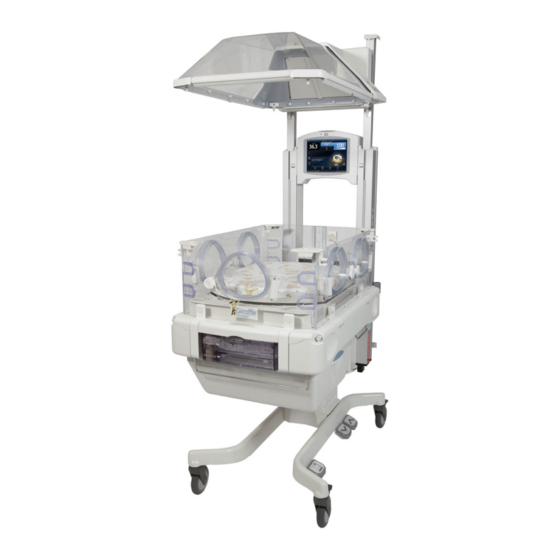
Giraffe OmniBed Carestation CS1
GE Giraffe OmniBed Carestation CS1 Manuals
Manuals and User Guides for GE Giraffe OmniBed Carestation CS1. We have
1
GE Giraffe OmniBed Carestation CS1 manual available for free PDF download: Service Manual
GE Giraffe OmniBed Carestation CS1 Service Manual (308 pages)
Brand:
GE
| Category:
Medical Equipment
| Size: 38.67 MB
Table of Contents
Table of Contents
5
Service Language Disclaimer
17
Safety and Regulatory Information
25
Warnings
25
Cautions
32
Symbols
34
Regulatory
39
User Responsibility
39
About this Manual
41
Intended Audience
41
Conventions
42
Technical Competence
42
Chapter 1: Functional Description
43
Control Board
43
FIGURE 1-1. Block Diagram
44
Relay Board
45
Infant Care Single Board Computer (ICSBC)
46
Alarm Board
47
Power Supply
47
Peripheral Components
47
Rail and Heater Door Switches
48
Datalink
48
Servo Controlled Oxygen Option
49
Humidifier
50
System Logs
50
Front View
51
Probe Panel
52
Side View
53
Rear View
54
Chapter 2: Installation and Service Checkout
55
Installation
55
Service Checkout
55
Mechanical Checks
55
Power Cord Condition
56
Parts
56
Wheel Operation
56
Bed Operation
56
Options Checks
57
Nurse Call Checks
58
Control Panel Checks
58
Humidifier Check
59
Oxygen Leak Tests
59
Oxygen Leak Test
59
Vent Fitting to O2 Sensor Leak Test
59
Supply Valve Leak Test
60
Scale Checks
61
Visual Inspection
61
Center Weight Check
61
Off Center Weight Check
61
FIGURE 2-1. Weight Placement Locations
62
Chapter 3: Calibration and Maintenance
63
Service Maintenance Schedule
63
FIGURE 3-1. Control Board Test Points
64
Special Tools
65
System Calibration
65
Humidifier Calibration
66
FIGURE 3-2. Cal RH
66
Servo Controlled Oxygen Calibration
67
Scale Calibration
67
FIGURE 3-3. Cal Scale
68
FIGURE 3-4. Initializing
69
FIGURE 3-5. Place Weight
69
FIGURE 3-6. Measuring
70
FIGURE 3-7. Enter Weight
70
Electrical Safety Tests
71
FIGURE 3-8. Calculating
71
FIGURE 3-9. Completion
71
Ground
72
Earth Leakage and Chassis Leakage Current
72
Leakage Current
72
Line Voltage Calibration
73
FIGURE 3-10. Cal Line Volt
73
Chapter 4: Understanding the Service Interface
75
Powering the Device
75
Accessing Service Mode
75
FIGURE 4-1. User Setup Screen
75
Change Password
76
Forgotten Passwords
76
Understanding the Service Interface Layout
77
Static Features
77
Preheat
77
FIGURE 4-2. Service Interface Layout
77
Pedals
78
General Information
78
Setup
78
FIGURE 4-3. Setup Screen
78
Calibration
79
Set Time
79
Upgrade
80
FIGURE 4-4. Set Time Screen
80
FIGURE 4-5. Upgrade Screen
80
Chapter 5: Troubleshooting
83
Troubleshooting Symptoms
83
Additional Troubleshooting Tips
91
Raising and Lowering the Canopy or Elevating Base
91
Incubator Heaters and Bed Safety Thermostat
91
Radiant Heater
92
Power Supplies
92
Troubleshooting Harness Cables 6600-0701-700 and 2075837-001
93
FIGURE 5-6. Exposing the Power Connector
93
Humidifier Heater/Safety Thermostat
95
Compartment Air Probe and Skin Temperature Probes
95
Heat Sink Sensor Thermistor
95
Elevating Base Motor and Canopy Motor
96
Troubleshooting the 50 Pin Ribbon Cable
96
Troubleshooting the Toroidal Transformer
97
Servo Controlled Oxygen
97
Status
97
Components Control
99
Servo Controlled Oxygen Alarm Messages
99
Servo Controlled Oxygen Troubleshooting Tips
103
Check Supply Valves and End Cap Safety Valve
103
Check Calibration Valve/Calibration Fan
103
Check Cooling Fan
103
Sensor Housing Temperature Sensor Temperature to Resistance Curve
104
Status
104
FIGURE 5-2. Status Screen
104
Switches
105
FIGURE 5-3. Status Screen
105
FIGURE 5-4. Status Screen
105
Error
106
FIGURE 5-5. Switch Diagnostic Diagram
106
Alarm Test
107
Diagnostic Readings
107
Status
107
FIGURE 5-6. Error Screen
107
FIGURE 5-7. Diagnostic Readings Screen
108
FIGURE 5-8. Diagnostic Readings Screen
108
DAC Voltage Test
109
Chapter 6: Alarms and System Failure Codes
111
Alarms
111
Compartment Sensor Failure Alarm
111
Patient Probe 1 Failure or Patient Probe 2 Failure Alarm
111
Patient Hot - Check Probe 1
112
Patient Cold - Check Probe 1
112
Canopy Pedal Disabled
112
Bed Height Pedals Disabled
113
Bed Raise Pedal Pressed
113
Bed Lower Pedal Pressed
113
Bed Heater Failure Alarm
114
Bed Raise/Lower Pedal Failure Alarm
115
Canopy Pedal Failure Alarm
115
Fan Always in High Speed Alarm
116
Fan Failure Alarm
116
Heater Doors Not Closed Alarm
117
Heater Doors Not Open Alarm
117
Humidity Failure Alarm
118
In Transition - Heat off Alarm
119
Motor Drive Failure Alarm
120
Power Failure (LED Indicator)
120
Radiant Heater Failure Alarm
121
Temperature out of Calibration Alarm
121
Up Pedal Pressed Alarm
122
Replace Clock Battery
122
System Failure Codes
122
System Failure 0
122
System Failure 1
122
System Failure 2
122
System Failure 3
122
System Failure 5
122
System Failure 6
122
System Failure 7
122
System Failure 12
123
System Failure 13
123
System Failure 14
124
System Failure 15
124
System Failure 16
124
System Failure 17
124
System Failure 18
125
System Failure 19
125
System Failure 20
125
System Failure 22
126
System Failure 23
126
System Failure 25
126
System Failure 26
128
System Failure 27
128
System Failure 28
128
System Failure 29
129
System Failure 30
129
System Failure 33
129
System Failure 34
130
System Failure 35
130
System Failure 36
130
System Failure 37
131
System Failure 38
131
System Failure 55
131
System Failure 60
132
System Failure 61
132
System Failure 62
132
System Failure 63
133
System Failure 70
133
System Failure 71
133
System Failure 81
134
System Failure 82
134
System Failure 83
134
System Failure 85
134
System Failure 98
134
System Failure 99
135
Chapter 7: Repair Procedures
137
Canopy Removal for Service
137
FIGURE 7-1. Heater Housing Cover and Soffit
138
FIGURE 7-2. Nuts
139
FIGURE 7-3. Access Holes
139
FIGURE 7-4. Canopy, Bracket, and Heater Housing
140
FIGURE 7-5. Two People Needed for this Step
140
FIGURE 7-6. Canopy Seal Parts
141
FIGURE 7-7. West Side Seal Parts
142
FIGURE 7-8. Using North Seal to Help Position Washers
143
FIGURE 7-9. Seal Cross-Section
143
FIGURE 7-10. North Seal Parts
144
FIGURE 7-11. Beveled Side of North Spacer Toward Canopy
144
FIGURE 7-12. Hole Fill Assembly (2X) for Canopies with Six Holes Across North End
145
FIGURE 7-13. South Seal Parts
146
FIGURE 7-14. South Corner Parts
147
FIGURE 7-15. North Corner Parts
147
FIGURE 7-16. Installing Rail Spacers
148
FIGURE 7-17. Soffit
150
FIGURE 7-18. Trimming the Soffit
150
FIGURE 7-19. Untrimmed and Trimmed Soffit
151
Canopy Seals Replacement Parts
152
Porthole Door Replacement
152
Display Head Removal
153
Rear Cover
153
Display Head
153
FIGURE 7-20. Rear Cover
153
Right Rail Assembly Repair Procedures
154
Removing the Right Upright (Motor Side)
154
FIGURE 7-21. Display Head Assembly
154
FIGURE 7-22. Disconnecting Heater Door Cable
155
FIGURE 7-23. Rail Decorative Strips, End Caps, and Wire Cover
156
Removing the Left Upright
157
FIGURE 7-24. Removing the Lift Motor
157
Right Rail Internal Repairs
159
Removing the Inner Rail Assembly
159
FIGURE 7-25. Right Rail Disassembly
159
Replacing Rollers and Tension Springs
160
Separating the Lift Rail from the Belt Channel
160
FIGURE 7-26. Rollers and Tensioning Spring
160
Replacing the Rail Buoyancy Springs
161
Reassembling the Right Upright
161
FIGURE 7-27. Replacing the Rail Buoyancy Springs
161
Left Rail Internal Repairs
163
Removing the Inner Rail Assembly
163
FIGURE 7-28. Left Inner Rail
163
Replacing the Rail Buoyancy Springs
164
FIGURE 7-29. Left Rail Springs and Spools
164
Replacing Rollers, Tension Springs, and Cable Carrier Links
165
Reassembling the Left Upright
165
FIGURE 7-30. Re-Attaching the Upright
165
Replacement of the Left Upright Heater Wire Harness/Cable Carrier Assembly
166
Removing and Disassembling the Rail
167
FIGURE 7-31. 3-Pin MAT-N-LOK Connector and Bushing
167
Reinstalling the Harness on the Left Rail
168
FIGURE 7-32. Cable Tie
168
FIGURE 7-33. Connector Drawing
168
Removing the Old Harness from the Cable Carrier Channel
169
Installing Harness on the Cable Carrier Channel
169
FIGURE 7-34. Opened Cable Guard Latches
169
FIGURE 7-35. Correct and Incorrect Cable Tie Usage
169
Reassembly
170
Radiant Heater Assembly Repair Procedures
170
Removing the Canopy/Heater Assembly
170
FIGURE 7-36. Lift Rail and Cable Carrier Channel Together
170
FIGURE 7-37. Canopy Alignment
171
Realigning the Canopy
172
Replacing the Radiant Heater
173
FIGURE 7-38. Radiant Heater Disassembly
173
Heater Door Spool Assembly
175
FIGURE 7-39. Heater Door Cable Adjustment
175
Heater Door Cable Adjustment
176
Spring Tube Assembly Replacement
176
FIGURE 7-40. Securing String to the Spring Tube
176
FIGURE 7-41. Removal of the Lower M5 Nut
177
FIGURE 7-42. Dog Point of the Set Screw
178
Compartment Sensor Repairs
179
Figure 7-43 Compartment Sensor Disassembly
179
Removing the Upper End Cap Spring
180
FIGURE 7-44. Top Rail End Cap
180
Lower Device Repairs
181
Removing the Chassis Cover with the Storage Drawer in Place
181
FIGURE 7-45. Chassis Bottom Cover
181
Incubator Fan, Fan Motor, and Optical Fan Sensor
182
FIGURE 7-46. Fan Motor
182
FIGURE 7-47. Heat Sink and Fan
182
Incubator Heater Replacement
183
End of the Bed
183
Removing the Incubator Heater Closest to the Control Panel End of the Bed
183
Elevating Base
184
FIGURE 7-48. Bed Disassembly
184
FIGURE 7-49. Elevating Base with Three-Shroud Assembly
185
Chassis Replacement
186
Bed Raise/Lower Pedal Switch
187
Canopy Foot Pedal Switch
187
Canopy Membrane Switch Replacement
187
Bed Tilt Brake Pad Replacement
188
FIGURE 7-50. Replacing the Tilt Brake Pad
188
Wheel Replacement
189
Humidifier Assembly Repairs
189
Disassembly
189
FIGURE 7-51. Humidifier Parts
190
Reassembly
191
Control Panel and Display Module Procedures
192
Probe Panel
192
FIGURE 7-52. Probe Panel
192
Power Fail Battery
193
Control Panel Components
193
Control Board
193
Figure 7-53 Electronics Enclosure
193
Relay Board
194
Solid State Relays
194
Power Supply
194
Toroidal Transformer
195
Canopy Lift Motor, ISO Transformer, Circuit Breakers, Power Switches, and Power Outlets
195
Servo Controlled Oxygen Service Procedures
196
Installing Oxygen Sensors
196
Replacing the Vent Screen
196
FIGURE 7-54. Installing Sensors
196
Sensor Housing Repairs
197
Sensor Housing Repairs: Boards, Calibration Fan Assembly, and Sensor Plug Assembly
197
FIGURE 7-55. Sensor Housing
197
Sensor Housing Repairs: Calibration Valve
198
Valve Housing Repairs
199
Valve Housing Repairs: Regulator Assembly
199
Valve Housing Repairs: Supply Valves
199
FIGURE 7-56. Valve Housing
199
End Cap Safety Valve
200
Servo Oxygen Board Repairs
200
FIGURE 7-57. End Cap Safety Valve
200
Display Module Repairs
201
Rear Cover
201
Carrier Plate Hardware
201
FIGURE 7-58. Rear Cover
201
Alarm Lens
202
Alarm Board
202
FIGURE 7-59. Alarm Lens
202
FIGURE 7-60. Alarm Board
202
FIGURE 7-61. Alarm Board Screws
203
FIGURE 7-62. Tab
203
FIGURE 7-63. Light Pipe
203
LCD Display Assembly
204
LCD Display Disassembly
204
FIGURE 7-64. Remove the Bezel
204
FIGURE 7-65. Temporary Support
204
FIGURE 7-66. Remove Thread Forming Screws
205
FIGURE 7-67. Set down Display
205
LCD Display Assembly
206
FIGURE 7-68. Harness Connectors
206
FIGURE 7-69. Ferrite Position
206
SBC (Single Board Computer) PCA
207
SBC Disassembly
207
FIGURE 7-70. Disconnect Power Harness
207
FIGURE 7-71. Disconnect Alarm PCA Harness
207
FIGURE 7-72. Remove EMI Shield
208
FIGURE 7-73. Remove SBC
208
SBC Assembly
209
Clock Battery Replacement
209
FIGURE 7-74. Do Not Use Screw
209
FIGURE 7-75. Screw Location
209
Display Harness Connections
210
Chapter 8: Illustrated Parts
213
Probe Housing
213
FIGURE 8-1. Probe Panel Assembly
214
Display Module
215
FIGURE 8-2. Display Module Disassembly
216
Electrical Enclosure
217
FIGURE 8-3. Electrical Enclosure
219
Electronic Enclosure Ground Stackup
220
FIGURE 8-4. Electrical Enclosure Ground Stackup
220
FIGURE 8-5. Electrical Enclosure Ground Stackup (Cont'D)
221
Harnesses
222
Relay Board Harness Connections
222
Control Board Harness Connections
223
Humidifier Transformer and RS-232
223
Bed and Side Panels
225
FIGURE 8-7. Bed
226
FIGURE 8-8. Side Panel (East/West)
228
FIGURE 8-9. Rear (North) and Front (South) Wall
230
Wire Covers
231
Radiant Heater and Canopy
231
FIGURE 8-10. Radiant Heater
232
FIGURE 8-11. Canopy
234
FIGURE 8-12. Enhanced Canopy Seal Parts
236
FIGURE 8-13. Heater Doors
238
Chassis
239
FIGURE 8-14. Upper Chassis
239
FIGURE 8-15. Lower Chassis
242
Humidifier
243
FIGURE 1-2. Humidifier
243
FIGURE 8-16. Humidifier Assembly
244
Elevating Base
245
FIGURE 8-17. Base and Elevating Column
246
Uprights and Lift Rail Components
247
FIGURE 8-18. Right (East) Upright Parts, Motor Side (Complete East Rail Assembly: 6600-0290-850) Motor Not Included
248
FIGURE 8-19. Belt Channel - 1 (Lift Motor Side)
250
FIGURE 8-20. Lift Rail (both Sides)
252
FIGURE 8-21. Rail End Caps
254
FIGURE 8-22. Left (West) Upright (Complete West Rail Assembly: 6600-0290-851)
256
Compartment Sensor
257
FIGURE 8-23. Compartment Sensor
257
Servo Control Oxygen
258
FIGURE 8-24. Servo Control Oxygen Sensor Housing Assembly (Servo O2 Upgrade Kit 6600-0678-800)
259
FIGURE 8-25. Servo Control Oxygen Valve Housing
261
FIGURE 8-26. Expansion Chamber/Heatsink Vent
262
FIGURE 8-27. Servo Control Oxygen Cooling Fan
263
FIGURE 8-28. Servo Control Oxygen PC Board
264
FIGURE 8-29. Manifold Endcap Safety Valve
265
Storage Drawer
266
FIGURE 8-30. Storage Drawer
266
Options
267
FIGURE 8-31. Instrument Shelf CN (M1082912)
267
FIGURE 8-32. Monitor Shelf CN (M1082910)
268
FIGURE 8-33. Cylinder Holders
269
FIGURE 8-34. Tubing Management Arm (6600-0837-800)
270
FIGURE 8-35. Dovetail Mount DIN Rail (6600-0659-803)
271
FIGURE 8-36. Silo Support Assembly (6600-0853-800)
272
FIGURE 8-37. Rotating I.V. Pole Assembly (6600-0851-800)
273
FIGURE 8-38. Dovetail Extension (6600-0852-800)
274
Options Pns
275
Labels
277
Label Illustrations
278
Warning Label Set
278
Connector Panel
279
Raise/Lower Pedal
280
Rating Label
280
Porthole Warning
280
Chassis Vent Servo O2
281
Servo O2 Maximum Pressure Labels
281
Weight Limit Warnings
282
Port Cover
283
Other Warnings
283
Canopy
283
PCB Layouts
284
FIGURE 8-39. Control Board (2080962-001)
284
FIGURE 8-41. Relay Board (Service Kit: 2080429-001)
286
Wiring Diagrams
287
FIGURE 8-42. Wiring Diagram: Control Board
287
FIGURE 8-43. Wiring Diagram: Elevating Base, Hood, and Motors
288
FIGURE 8-44. Wiring Diagram: Electrical Enclosure
289
FIGURE 8-45. Wiring Diagram: Control Panel
290
FIGURE 8-46. Wiring Diagram: Incubator and Warmer Heater
291
FIGURE 8-47. Wiring Diagram: Servo Humidifier
292
FIGURE 8-48. Wiring Diagram: Servo Control Oxygen
293
Appendix A: Compartment and Skin Probe Characteristics
295
Appendix B: Specifications
297
Appendix C: RS-232 Serial Data
301
Connector
301
Cable Requirements
301
Nurse Call
302
Connector
302
Nurse Call Signals
303
Index
305
Advertisement
Advertisement
Related Products
GE auisys cs2
GE CIC Pro
GE Cardiolab II Plus
GE LOGIQ C3 Premium
GE CARESCAPE
GE LOGIQ C9 Series
GE Corometrics 173
GE Centiva/5 Plus
GE LOGIQ C5 PRO
GE Advantium CSB913
GE Categories
Refrigerator
Ranges
Microwave Oven
Air Conditioner
Dishwasher
More GE Manuals
Login
Sign In
OR
Sign in with Facebook
Sign in with Google
Upload manual
Upload from disk
Upload from URL