Sign In
Upload
Manuals
Brands
GE Manuals
UPS
FGC TLE 150 UL S1
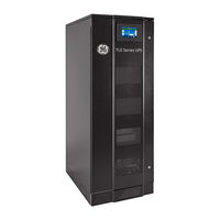
GE FGC TLE 150 UL S1 UPS Manuals
Manuals and User Guides for GE FGC TLE 150 UL S1 UPS. We have
1
GE FGC TLE 150 UL S1 UPS manual available for free PDF download: Manual
GE FGC TLE 150 UL S1 Manual (509 pages)
40-150 KVA/KW, 480 VAC Three phase Highly Efficient and Scalable
Brand:
GE
| Category:
UPS
| Size: 77.26 MB
Table of Contents
Critical Power Table of Content
21
Table of Contents
21
Important Safety Instructions
22
Layout
25
Layout Tle Scalable Series 40 - 150
25
Environment
27
Recycling Instructions
27
Installation
28
Transport
28
Dimensions and Weights TLE Scalable Series 40 - 150
29
Storage of Battery
31
Storage
31
Storage of the UPS
31
Delivery
31
Place of Installation
32
UPS Location
32
Battery Location
34
Ventilation and Cooling
35
Unpacking
36
Electrical Wiring
38
Utility Input Connection
38
Input/Output over Current Protection and Wire Sizing
39
Data for Input/Output and Battery over Current Protection and Wire Sizing
40
Installation Requirements
43
Wiring Connection
46
TLE Scalable Series 40 - 150 - Power Connection with Common Input Utility
47
TLE Scalable Series 40 - 150 - Power Connection with Dual Input Utility
49
Battery Cabinet Connection to TLE Scalable Series 40 - 150
51
Use of TLE Scalable Series 40 - 150 in SEM Operation Mode (Super Eco Mode)
53
Use of TLE Scalable Series 40 - 150 as Frequency Converter
54
Rpa Parallel System Connection
55
Power Wiring of Parallel Units
55
Parallel Control Bus Connection
56
Control Bus Cable Location
58
Epo - Emergency Power Off" Command Connection
60
Connectivity Interface
61
SERIAL PORT J35Μp - RS232 (SUB D, FEMALE 9 PIN)
62
Customer Interface Board
63
X1 Terminal Block - Output Signals on Voltage-Free Contacts
64
X1 Terminal Block - Programmable Input Free Contacts
64
X1 Terminal Block - Gen Set Signalling (GEN ON)
65
X1 Terminal Block - AUX External Maintenance Bypass
65
X1 Terminal Block - Sem/Iemi Control Signal
65
3-Ph Snmp/Web Plug-In Adapter" Board
66
Options
67
Top Cable Entry/Exit Sidecar and Top hat Fascia
67
Notes
69
Notes Form
69
Critical Power Table of Content Page
81
Important Safety Instructions
82
Layout
85
Layout Tle Scalable Series 40 - 150
85
Introduction
86
Description
87
Block Diagram and Main Elements
88
Normal VFI Operation Mode (Voltage Frequency Independent)
89
Operation Modes
89
SEM Operation Mode (Super Eco Mode)
89
Utility Failure Operation
90
Utility Recovery Operation
90
Automatic Bypass
91
Introduction to the RPA Parallel System
92
Rpa Parallel System Operation
92
Features of RPA Parallel System
93
Load Sharing
93
Synchronization
93
System Control
93
Iemi Operation Mode (Option)
94
Ups Paralleled on the same Battery
95
Service and Technical Support
96
Warranty
96
Recycling Instructions
97
Control Panel
98
Home Screen
99
Lcd Screen
99
Description of the Selection Keys
100
Description of the Signaling Leds
101
Measures
104
Events
108
Alarms List
110
Events (Alarms and Messages)
110
Messages List
115
Setup
118
Commands
124
Rpa Parallel System
128
Operation
130
Initial Start-Up of the TLE Scalable Series 40 - 150
131
Procedures for Single Tle Scalable Series 40 - 150
131
Complete UPS Shut-Down
135
Restore to Normal Operation after "System Shutdown" with Load Not Supplied
136
Restore to Normal Operation after "EPO - Emergency Power Off" with Load Not Supplied
138
Initial Start-Up of the TLE Scalable Series 40 - 150 as Frequency Converter
140
Procedures Single Tle Scalable Series 40 - 150 Functioning as Frequency Converter
140
Complete Shut-Down of the TLE Scalable Series 40 - 150 as Frequency Converter
144
Restore to Normal Operation after "System Shutdown" with Load Not Supplied
145
Restore to Normal Operation after "EPO - Emergency Power Off" with Load Not Supplied
147
Procedures for Tle Scalable Series 40 - 150 Parallel System
149
TLE Scalable Series 40 - 150 Parallel System Start-Up
149
Separate a UPS Unit from the Redundant Parallel System
154
Reconnect a UPS Unit to Redundant Parallel System
156
Complete Parallel System Shut-Down
158
Restore to Normal Operation after "System Shutdown" with Load Not Supplied
159
Restore to Normal Operation after "EPO - Emergency Power Off" with Load Not Supplied
161
Connectivity Options
163
Options
163
Options in Additional Cabinets
163
Options in Ups Cabinet
163
Fans and Ventilation
164
Maintenance
164
Other Components with Limited Lifetime
164
Service Check
164
Battery
165
Preventive Maintenance Program
165
UPS Room Conditions and Temperature
165
Notes
166
Notes Form
166
Critical Power Table of Content
186
Important Safety Instructions
187
Layout
190
Environment
194
Recycling Instructions
194
Installation
195
Transport
195
Dimensions and Weights TLE Series 160 - 500
196
Delivery
197
Storage
197
Storage of Battery
197
Storage of the UPS
197
Place of Installation
198
UPS Location
198
Battery Location
201
Ventilation and Cooling
202
Unpacking
203
Electrical Wiring
205
Utility Input Connection
205
Input/Output over Current Protection and Wire Sizing
206
Data for Input/Output and Battery over Current Protection and Wire Sizing
207
Installation Requirements
210
Wiring Connection
213
TLE Series 160 - 200 - 225 - 250 Power Connection with Common Input Utility
216
TLE Series 160 - 200 - 225 - 250 Power Connection with Dual Input Utility
218
TLE Series 300 - 400 - 500 Power Connection with Common Input Utility
221
TLE Series 300 - 400 - 500 Power Connection with Dual Input Utility
223
Use of TLE Series 160 - 500 in Eboost™ Operation Mode
226
Use of TLE Series 160 - 500 as Frequency Converter
227
Power Wiring of Parallel Units
228
Rpa Parallel System Connection
228
Parallel Control Bus Connection
229
Control Bus Cable Location
231
Epo - Emergency Power Off" Command Connection
233
Customer Interface
235
SERIAL PORT J35Μp - RS232 (SUB D, FEMALE 9 PIN)
236
Customer Interface Board
237
Connector J1 - RJ45 8P8C
238
X1 Terminal Block - Output Signals on Voltage-Free Contacts
238
X1 Terminal Block - Programmable Input Free Contacts
238
X1 Terminal Block - Gen Set Signaling (GEN ON)
239
X2 Terminal Block - "EPO - Emergency Power off
239
X1 Terminal Block - AUX External Maintenance Bypass
240
X1 Terminal Block - Eboost/Iemi Control Signal
240
Notes
241
Notes Form
241
Critical Power Table of Content Page
246
Important Safety Instructions
247
Layout
250
Introduction
252
Description
253
Block Diagram and Main Elements
254
Eboost™ Operation Mode (Option)
255
Normal VFI Operation Mode (Voltage Frequency Independent)
255
Operation Modes
255
Utility Failure Operation
256
Utility Recovery Operation
256
Automatic Bypass
257
Introduction to the RPA Parallel System
258
Rpa Parallel System Operation
258
Features of RPA Parallel System
259
Load Sharing
259
Synchronization
259
System Control
259
Iemi Operation Mode (Option)
260
Ups Paralleled on the same Battery
261
Service and Technical Support
262
Warranty
262
Recycling Instructions
263
Control Panel
264
Home Screen
265
Lcd Screen
265
Description of the Selection Keys
266
Description of the Signaling Leds
267
Measures
270
Events
274
Alarms List
276
Events (Alarms and Messages)
276
Messages List
281
Setup
284
Commands
290
Rpa Parallel System
294
Operation
296
Procedures for Single Tle Series 160 - 500
296
Initial Start-Up of the TLE Series 160 - 500
297
Complete UPS Shut-Down
301
Restore to Normal Operation after "System Shutdown" with Load Not Supplied
302
Restore to Normal Operation after "EPO - Emergency Power Off" with Load Not Supplied
304
Initial Start-Up of the TLE Series 160 - 500 as Frequency Converter
306
Procedures Single Tle Series 160 - 500 Functioning as Frequency Converter
306
Complete Shut-Down of the TLE Series 160 - 500 as Frequency Converter
310
Restore to Normal Operation after "System Shutdown" with Load Not Supplied
311
Restore to Normal Operation after "EPO - Emergency Power Off" with Load Not Supplied
313
Procedures for Tle Series 160 - 500 Parallel System
315
TLE Series 160 - 500 Parallel System Start-Up
315
Separate a UPS Unit from the Redundant Parallel System
320
Reconnect a UPS Unit to Redundant Parallel System
322
Complete Parallel System Shut-Down
324
Restore to Normal Operation after "System Shutdown" with Load Not Supplied
325
Restore to Normal Operation after "EPO - Emergency Power Off" with Load Not Supplied
327
Connectivity Options
329
Options
329
Options in Ups Cabinet
329
Fans and Ventilation
330
Maintenance
330
Other Components with Limited Lifetime
330
Service Check
330
Battery
331
Preventive Maintenance Program
331
UPS Room Conditions and Temperature
331
Notes
332
Notes Form
332
Critical Power Table of Content
353
Important Safety Instructions
354
Layout
357
Layout Tle Series 625 & 750
357
Layout Tle Series 1000
359
Environment
361
Recycling Instructions
361
Installation
362
Transport
362
Dimensions and Weights TLE Series 625 - 750 - 1000
363
Delivery
364
Storage
364
Storage of Battery
364
Storage of the UPS
364
Place of Installation
365
UPS Location
365
Battery Location
369
Ventilation and Cooling
370
Unpacking
371
Cabinets Positioning and Interconnection
373
Inter Cabinet Connections
373
Bus Bars Interconnection
375
Control Cables Interconnection
377
Electrical Wiring
381
Utility Input Connection
381
Input/Output over Current Protection and Wire Sizing
382
Data for Input/Output and Battery over Current Protection and Wire Sizing
383
Installation Requirements
385
Wiring Connection
388
TLE Series 625 & 750 - Power Connection with Common Input Utility
392
TLE Series 625 & 750 - Power Connection with Dual Input Utility
394
TLE Series 1000 - Power Connection with Common Input Utility
397
TLE Series 1000 - Power Connection with Dual Input Utility
399
Use of TLE Series 625 - 750 - 1000 in Eboost™ Operation Mode
402
Use of TLE Series 625 - 750 - 1000 as Frequency Converter
403
Power Wiring of Parallel Units
404
Rpa Parallel System Connection
404
Parallel Control Bus Connection
405
Control Bus Cable Location
407
Epo - Emergency Power Off" Command Connection
409
Customer Interface
411
SERIAL PORT J35Μp - RS232 (SUB D, FEMALE 9 PIN)
412
Customer Interface Board
413
Connector J1 - RJ45 8P8C
414
X1 Terminal Block - Output Signals on Voltage-Free Contacts
414
X1 Terminal Block - Gen Set Signaling (GEN ON)
415
X2 Terminal Block - "EPO - Emergency Power off
415
X1 Terminal Block - AUX External Maintenance Bypass
416
X1 Terminal Block - Eboost/Iemi Control Signal
416
Notes
417
Notes Form
417
Table of Contents
422
Important Safety Instructions
423
Layout
426
Layout Tle Series 625 & 750
426
Layout Tle Series 1000
427
Introduction
428
Description
429
Block Diagram and Main Elements
430
Eboost™ Operation Mode (Option)
431
Normal VFI Operation Mode (Voltage Frequency Independent)
431
Operation Modes
431
Utility Failure Operation
432
Utility Recovery Operation
432
Automatic Bypass
433
Introduction to the RPA Parallel System
434
Rpa Parallel System Operation
434
Features of RPA Parallel System
435
Load Sharing
435
Synchronization
435
System Control
435
Iemi Operation Mode (Option)
436
Ups Paralleled on the same Battery
438
Service and Technical Support
439
Warranty
439
Recycling Instructions
440
Control Panel
441
Home Screen
442
Lcd Screen
442
Description of the Selection Keys
443
Description of the Signaling Leds
444
Measures
447
Events
451
Alarms List
453
Events (Alarms and Messages)
453
Messages List
458
Setup
461
Commands
467
Rpa Parallel System
471
Operation
473
Initial Start-Up of the TLE Series 625 - 750 - 1000
474
Procedures for Single Tle Series 625 - 750 - 1000
474
Complete UPS Shut-Down
478
Restore to Normal Operation after "System Shutdown" with Load Not Supplied
479
Restore to Normal Operation after "EPO - Emergency Power Off" with Load Not Supplied
481
Initial Start-Up of the TLE Series 625 - 750 - 1000 as Frequency Converter
483
Complete Shut-Down of the TLE Series 625 - 750 - 1000 as Frequency Converter
487
Restore to Normal Operation after "System Shutdown" with Load Not Supplied
488
Restore to Normal Operation after "EPO - Emergency Power Off" with Load Not Supplied
490
Procedures for Tle Series 625 - 750 - 1000 Parallel System
492
TLE Series 625 - 750 - 1000 Parallel System Start-Up
492
Separate a UPS Unit from the Redundant Parallel System
497
Reconnect a UPS Unit to Redundant Parallel System
499
Complete Parallel System Shut-Down
501
Restore to Normal Operation after "System Shutdown" with Load Not Supplied
502
Restore to Normal Operation after "EPO - Emergency Power Off" with Load Not Supplied
504
Connectivity Options
506
Options
506
Options in Ups Cabinet
506
Fans and Ventilation
507
Maintenance
507
Other Components with Limited Lifetime
507
Service Check
507
Battery
508
Preventive Maintenance Program
508
UPS Room Conditions and Temperature
508
Notes
509
Notes Form
509
Advertisement
Advertisement
Related Products
GE TLE 160
GE FGC TLE 100 UL S1
GE FGC TLE 120 UL S1
GE TLE 1000 UL S2
GE TLE 400
GE TLE 200
GE TLE Scalable 80
GE TLE Scalable 100
GE TLE series 600
GE TLE series 800
GE Categories
Refrigerator
Ranges
Microwave Oven
Air Conditioner
Dishwasher
More GE Manuals
Login
Sign In
OR
Sign in with Facebook
Sign in with Google
Upload manual
Upload from disk
Upload from URL