Sign In
Upload
Manuals
Brands
GE Manuals
Medical Equipment
5265742
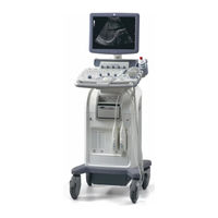
GE 5265742 Medical Equipment Manuals
Manuals and User Guides for GE 5265742 Medical Equipment. We have
1
GE 5265742 Medical Equipment manual available for free PDF download: Basic Service Manual
GE 5265742 Basic Service Manual (164 pages)
Brand:
GE
| Category:
Medical Equipment
| Size: 7.78 MB
Table of Contents
Table of Contents
15
Overview
25
Purpose of Service Manual
25
Typical Users of the Basic Service Manual
26
Purpose of Operator Manual(S)
26
LOGIQ C2/C3/C5 Models Covered by this Manual
26
Important Conventions
28
Conventions Used in Book
28
Standard Hazard Icons
29
Product Icons
29
Safety Considerations
30
Introduction
30
Human Safety
30
Mechanical Safety
30
Electrical Safety
31
Label Locations
31
Dangerous Procedure Warnings
32
Returning/Shipping Probes and Repair Parts
32
EMC, EMI, and ESD
33
Electromagnetic Compatibility (EMC)
33
CE Compliance
33
Electrostatic Discharge (ESD) Prevention
33
Customer Assistance
34
Contact Information
34
System Manufacturer
35
Factory Site
35
Site Preparations
37
Overview
37
Purpose of Chapter 2
37
General Console Requirements
38
Console Environmental Requirements
38
Electrical Requirements
38
EMI Limitations
40
Scan Probe Environmental Requirements
41
Facility Needs
42
Purchaser Responsibilities
42
Required Features
43
Recommended and Alternate Ultrasound Room Layout
44
Networking Pre-Installation Requirements
45
System Setup
47
Overview
47
Purpose of Chapter 3
47
Setup Reminders
48
Average Installation Time
48
Installation Warnings
49
Safety Reminders
50
Receiving and Unpacking the Equipment
51
Moving into Position
52
Product Locator Installation Card
52
Preparing for Installation
53
Verify Customer Order
53
Physical Inspection
53
EMI Protection
53
Completing the Installation
54
Power on / Boot up
54
Power Off/ Shutdown
54
Transducer Connection
55
System Configuration
56
System Specifications
56
Electrical Specifications
56
On-Board Optional Peripherals
57
Connecting Cables
58
Peripherals/Accessories Connector Panel
58
Available Probes
64
Software/Option Configuration
64
Connectivity Installation Worksheet
65
Loading Base Image Software
66
Software Version Check out
67
Functional Check-Out
67
Paperwork
68
Product Locator Installation
68
User Manual(S)
68
Overview
69
Purpose for Chapter 4
69
Required Equipment
69
General Procedure
70
Power On/Boot up
70
Power Off/ Shutdown
70
Archiving and Loading Presets
72
Adjusting the Display Monitor
73
System Features
74
B Mode Checks
77
M Mode Controls
80
Doppler Mode Checks
83
Color Flow Mode Checks
87
Basic Measurements
91
Probe/Connectors Usage
92
Using Cine
92
Image Management (QG)
93
Backup and Restore Database, Preset Configurations and Images
94
Software Configuration Checks
103
Peripheral Checks
103
Components and Functions (Theory)
105
Overview
105
Purpose of Chapter 5
105
Block Diagram
105
System Diagram
106
Software Diagram
107
Common Service Platform
108
Introduction
108
Diagnostics/Troubleshooting
111
Overview
111
Purpose of Chapter 7
111
Gathering Trouble Data
112
Overview
112
Collect Vital System Information
112
Collect a Trouble Image with Logs
113
USB Quick Save
114
Overview
114
Check and Record the Print or Store Key Function
114
Setting the Print or Store Key to USB Quick Save
115
Screen Captures
116
Check and Record the Store Key Function
116
Setting the Store Key to Screen Capture
116
Capturing a Screen
116
Reset the Store Key to Customer's Functionality
118
Common Diagnostics
119
Utilities
119
PC Diagnostics (Non-Interactive Tests)
120
PC Diagnostics (Interactive Tests)
121
Restart LOGIQ C Series after Diagnostics
121
Network Configuration
122
Replacement Procedures
125
Overview
125
Purpose of Chapter 8
125
Disassembly/Re-Assembly
126
Warning and Caution
126
Air Filter and Knob Screw (FRU No. 5030)
126
Loading Base Image Software
128
Renewal Parts
131
Overview
131
Purpose of Chapter 9
131
List of Abbreviations
131
Renewal Parts Lists
131
Equipment Models Covered in this Chapter
132
Operator Console Assy
133
Keyboard Assy
133
Accessories and Kits
134
Manuals
136
Probes
138
Care & Maintenance
139
Overview
139
Periodic Maintenance Inspections
139
Purpose of Chapter 10
139
Why Do Maintenance
140
Keeping Records
140
Quality Assurance
140
Maintenance Task Schedule
140
How Often Should Care & Maintenance Tasks be Performed
140
Tools Required
142
Standard GE Tool Kit
142
Special Tools, Supplies and Equipment
144
Input Power
145
Cleaning
145
Physical Inspection
145
Outlet Test - Wiring Arrangement - USA & Canada
146
Grounding Continuity
147
Chassis Leakage Current Test
149
Isolated Patient Lead (Source) Leakage-Lead to Lead
152
Isolated Patient Lead (Sink) Leakage-Isolation Test
152
Probe Leakage Current Test
154
When There's too Much Leakage Current
158
Advertisement
Advertisement
Related Products
GE 5268701
GE 5269076
GE 5263818
GE 5264909
GE 5265707
GE 5268024-2
GE 5262932
GE 5268906
GE 5245477
GE 5205000-8
GE Categories
Refrigerator
Ranges
Microwave Oven
Air Conditioner
Dishwasher
More GE Manuals
Login
Sign In
OR
Sign in with Facebook
Sign in with Google
Upload manual
Upload from disk
Upload from URL