Sign In
Upload
Manuals
Brands
Fujitsu Manuals
Server
PRIMERGY CX400 M4
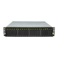
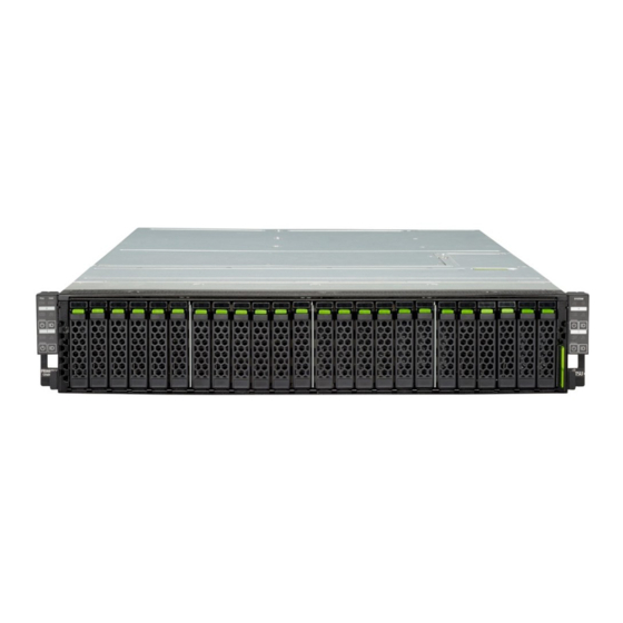
Fujitsu PRIMERGY CX400 M4 Manuals
Manuals and User Guides for Fujitsu PRIMERGY CX400 M4. We have
4
Fujitsu PRIMERGY CX400 M4 manuals available for free PDF download: Upgrade And Maintenance Manual, Operating Manual, Disassembly And Recycling Document
Fujitsu PRIMERGY CX400 M4 Upgrade And Maintenance Manual (194 pages)
Brand:
Fujitsu
| Category:
Server
| Size: 10.16 MB
Table of Contents
Server Enclosure
1
Copyright and Trademarks
2
Table of Contents
7
1 Introduction
13
Notational Conventions
14
2 Before You Start
15
Classification of Procedures
16
Customer Replaceable Units (CRU)
16
Upgrade and Repair Units (URU)
17
Field Replaceable Units (FRU)
18
Average Task Duration
19
Tools You Need at Hand
20
Documents You Need at Hand
21
Documents for the Server Enclosure
22
Documents for the Server Nodes
24
3 Important Information
25
Safety Instructions
25
Energy Star
34
CE Conformity
34
Environmental Protection
35
4 Basic Hardware Procedures
37
Using Diagnostics Information
37
Locating the Defective Server
37
Determining the Error Class
38
Customer Self Service (CSS) Indicator
38
Global Error Indicator
39
Locating the Defective Component
39
Local Diagnostic Indicators on the Front
39
Shutting down the Server Node
40
Disconnecting the Power Cord
41
Extending/Removing the Server Enclosure out of the Rack
42
Preliminary Steps
42
Extending the Server Enclosure out of the Rack
43
Removing the Server Enclosure out of the Rack
43
Removing Server Nodes from the Server Enclosure
46
Removing the CX2550 M4 / CX2560 M4 Server Node
46
Removing the CX2570 M4 Server Node
48
Removing the Server Node Dummy Module
49
Opening the Server Enclosure
50
Opening the Fan Cover
50
Opening the Midplane Cover
51
Closing the Server Enclosure
51
Installing the Midplane Cover
52
Installing the Fan Cover
53
Installing the Server Node Dummy Module
54
Installing the Server Node in the Server Enclosure
55
Basic Information
55
Installing the CX2550 M4/CX2560 M4 Server Node
58
Installing the CX2570 M4 Server Node
60
Mounting the Server Enclosure in the Rack
61
Removing the Inner Rail from the Carrier Rails
61
Attaching the Carrier Rails to the Server Enclosure
63
Installing the Carrier Rails
64
Lift the Server into the Rack Cabinet
65
Installing the Cable Management Arm (CMA)
69
Connecting the Power Cord
71
Switching on the Server Node(S)
72
5 Basic Software Procedures
73
Starting the Maintenance Task
73
Switching on the ID Indicator
73
Completing the Maintenance Task
74
Switching off the ID Indicator
74
Verifying System Information Backup / Restore
75
Performing a RAID Array Rebuild
75
Using the Chassis ID Prom Tool
76
Viewing and Clearing the System Event Log (SEL)
77
Viewing the SEL
77
Clearing the SEL
78
Performing a Fan Test
79
Updating Serverview RAID Manager
80
6 Power Supply Unit (PSU)
81
Basic Information
81
General Equipping Rules
82
Replacing the Hot-Plug PSU
83
Preliminary Steps
83
Removing the Hot-Plug PSU
84
Installing the Hot-Plug PSU
85
Concluding Steps
86
Removing and Installing the PSU Dummy Module
87
Removing the PSU Dummy Module
87
Installing the PSU Dummy Module
88
7 Hard Disk Drives (HDD), Solid State Drives (SSD) and 2.5-Inch Pcie-SSD
89
Basic Information
90
General Equipping Rules
90
HDD/SSD Install Order
91
HDD/SSD Backplane Types
92
HDD/SSD Cage Bezels
94
Installing 2.5-Inch HDD/SSD Modules
95
Preliminary Steps
95
Removing a 2.5-Inch HDD/SSD Dummy Module
96
Installing a 2.5-Inch HDD/SSD Module
97
Concluding Steps
97
Removing 2.5-Inch HDD/SSD Modules
98
Preliminary Steps
98
Removing a 2.5-Inch HDD/SSD Module
99
Installing a 2.5-Inch HDD/SSD Dummy Module
100
Replacing a 2.5-Inch HDD/SSD Module
101
Preliminary Steps
102
Removing a 2.5-Inch HDD/SSD Module
102
Installing a 2.5-Inch HDD/SSD Module
102
Concluding Steps
102
Replacing the 2.5-Inch HDD/SSD SAS/SATA Backplane
103
Preliminary Steps
103
Removing the Fan Modules Cage
104
Removing the 2.5-Inch HDD/SSD Backplane
105
Installing the 2.5-Inch HDD/SSD Backplane
106
Installing the Fan Modules Cage
107
Concluding Steps
110
Installing the HDD/SSD Bridge Board
111
Preliminary Steps
111
Installing the HDD/SSD Bridge Board
112
Concluding Steps
113
Replacing the HDD/SSD Bridge Board
114
Preliminary Steps
114
Removing the HDD/SSD Bridge Board
115
Installing the HDD/SSD Bridge Board
116
Concluding Steps
117
Changing HDD/SSD Cage Bezels
118
Preliminary Steps
118
Removing the HDD/SSD X6 Front Bezel
119
Removing the HDD/SSD X6 Front Bezel (Screw Type)
120
Removing the HDD/SSD X4 Front Bezel
121
Installing the HDD/SSD X6 Front Bezel
122
Installing the HDD/SSD X6 Front Bezel (Screw Type)
122
Installing the HDD/SSD X4 Front Bezel
124
Concluding Steps
125
8 System Fan Module
127
Basic Information
128
Replacing the System Fan Module
130
Preliminary Steps
130
Removing the Fan Module
131
Installing the Fan Module
133
Concluding Steps
141
Replacing the Fan Cable
142
Preliminary Steps
142
Disconnecting the Fan Cable
143
Connecting the Fan Cable
144
Concluding Steps
148
9 Midplane Kit
149
Basic Information
150
Replacing the Midplane Kit
151
Preliminary Steps
151
Removing the Midplane Kit
152
Installing the Midplane Kit
153
Concluding Steps
155
10 Front Panel
157
Basic Information
158
Replacing the Left Front Panel
159
Preliminary Steps
159
Removing the Front Panel
160
Installing the Front Panel
162
Concluding Steps
163
Replacing the Right Front Panel
164
Preliminary Steps
164
Removing the Front Panel
164
Installing the Front Panel
166
Concluding Steps
167
Replacing the Left Front Panel Cable
168
Preliminary Steps
168
Removing the Front Panel Cable
169
Installing the Front Panel Cable
170
Concluding Steps
171
Replacing the Right Front Panel Cable
172
Preliminary Steps
172
Removing the Front Panel Cable
173
Installing the Front Panel Cable
174
Concluding Steps
175
11 Cabling
177
Cabling Overview
177
Cabling
178
12 Appendix
179
Mechanical Overview
179
Server Enclosure Front
179
Rear Overview with CX2550 M4 / CX2560 M4 Server Nodes
180
Rear Overview with CX2570 M4 Server Nodes
181
Enclosure Interior
182
Controls and Indicators
183
Controls and Indicators on the Front of the Server Enclosure
183
Indicators on the Front Panel (Enclosure-Related)
185
Indicators on the Front Panel (Node-Related)
187
ID Card
189
Indicators on the Hdds
191
Indicator on Hot-Plug PSU
192
Fan Indicators
193
Indicators of the Server Nodes
193
Minimum Startup Configuration
194
Advertisement
Fujitsu PRIMERGY CX400 M4 Operating Manual (84 pages)
Server Enclosure
Brand:
Fujitsu
| Category:
Enclosure
| Size: 2.7 MB
Table of Contents
Table of Contents
7
1 Introduction
9
Notational Conventions
9
2 Before You Start
11
Documentation Overview
11
Documents for the Server Enclosure
11
Documents for the Server Nodes
13
3 Product Description
15
Overview of the Server Enclosure
16
Server Enclosure Front
16
Server Enclosure Rear
18
Features
19
Controls and Indicators
21
Controls and Indicators on the Server Enclosure Front
21
Controls on the Front Panel
21
Indicators on the Front Panel
22
Indicators on the Hot-Plug HDD/SSD Module
27
Controls and Indicators on the Server Enclosure Rear
28
Indicator on Hot-Plug PSU
28
Indicators of the Server Nodes
28
4 Important Information
29
Safety Instructions
29
Energy Star
38
CE Conformity
38
FCC Class a Compliance Statement
39
Environmental Protection
40
5 Starting up
43
Installation Steps, Overview
44
Unpacking the Server Enclosure
46
Installing/Removing the Server Enclosure in the Rack
47
Installing the Server Enclosure in the Rack
49
Removing the Server Enclosure out of the Rack
57
Connecting Cables
60
Notes on Connecting/Disconnecting Cables
60
Connecting the Power Cord
61
Switching on the Multi-Node Server System for the First Time
61
6 Operation
63
Switching the Multi-Node Server System on and off
63
Removing 2.5-Inch HDD/SSD Modules
66
Removing a 2.5-Inch HDD/SSD Module
66
Installing a 2.5-Inch HDD/SSD Dummy Module
67
Removing the Hot-Plug PSU
68
Installing a Server Node
69
Removing the Server Node Dummy Module
69
Installing the CX2550 M4/M5 or CX2560 M4/M5 Server Node
69
Installing the CX2570 M4/M5 Server Node
72
Cleaning the Server Enclosure
73
7 Troubleshooting and Tips
75
8 Technical Data
77
9 Warranty and Service
83
Fujitsu PRIMERGY CX400 M4 Operating Manual (72 pages)
Server Enclosure
Brand:
Fujitsu
| Category:
Server
| Size: 2.39 MB
Table of Contents
Server Enclosure
1
Copyright and Trademarks
2
Table of Contents
5
1 Introduction
7
Concept and Target Groups for this Manual
7
Documentation Overview
8
Notational Conventions
9
2 Functional Overview
11
Features
11
Server Enclosure Specification
13
3 Installation Steps, Overview
19
4 Important Information
21
Safety Instructions
21
Energy Star
30
CE Conformity
30
FCC Class a Compliance Statement
31
Environmental Protection
32
Transporting the Server Enclosure
33
Notes on Installing the Server Enclosure in the Rack
34
5 Hardware Installation
35
Unpacking the Server Enclosure
36
Installing/Removing the Server Enclosure In/From the Rack
37
Mounting the Server Enclosure in the Rack
39
Removing the Server Enclosure out of the Rack
46
Connecting the Server Enclosure to the Mains
50
Notes on Connecting/Disconnecting Cables
51
6 Starting up and Operation
53
Overview of the Server Enclosure
53
Front Overview with CX2550 M4 Server Nodes
53
Front Overview with CX2560 M4 / CX2570 M4 Server Nodes
54
Rear Overview with CX2550 M4 or CX2560 M4 Server Nodes
55
Rear Overview with CX2570 M4 Server Nodes
56
Controls and Indicators
57
Front of the Server Enclosure
57
Indicators on the Front Panel (Enclosure-Related)
58
Indicators on the Front Panel (Node-Related)
60
ID Card
62
Indicators on the Hdds
63
Indicator on Hot-Plug PSU
64
Indicators of the Server Nodes
64
Switching the Multi-Node Server System on and off
65
Cleaning the Server Enclosure
68
7 Property and Data Protection
69
BIOS Setup Security Functions
69
8 Troubleshooting and Tips
71
Power-On Indicator Remains Unlit
71
Drives Reported as "Dead" When Starting System
72
Added Drive Reported as Defective
72
Advertisement
Fujitsu PRIMERGY CX400 M4 Disassembly And Recycling Document (76 pages)
Enclosure & Nodes
Brand:
Fujitsu
| Category:
Server
| Size: 3.68 MB
Table of Contents
Table of Contents
5
Recycling Information
7
Disassembly of the Server Enclosure
9
Removing Server Nodes from the Server Enclosure
9
Removing the ID Card and Server Cover
12
Removing the Hot-Plug PSU
16
Removing Fan Modules
17
Removing the Fan Cage
19
Removing the Midplane Kit
20
Removing 2.5-Inch HDD/SSD Modules
22
Removing 2.5-Inch HDD Backplanes
24
Removing the HDD/SSD Bridge Board
25
Removing Front Bezels
26
Removing the Front Panel Modules
28
Disassembly of the Server Nodes
30
Removing the SXM2 Extension Tray, SXM2 Modules and LC Kit
30
Removing the GPGPU Extension Tray and Gpgpus
42
Removing Riser Modules and Expansion Cards
49
Removing an FBU
54
Removing an OCP Mezzanine Card
56
Removing Main Memory Modules
57
Removing the Heat Sink and CPU (Air Cooling)
59
Removing the Heat Sink and CPU (LC)
61
Removing the Irmc Microsd Card
69
Removing M.2 Ssds
69
Removing the Dual Microsd 64GB Enterprise
70
Removing the TPM and System Board
72
Removing the Battery
76
Advertisement
Related Products
Fujitsu PRIMERGY CX420 S1
Fujitsu PRIMERGY CX400 M1
Fujitsu PRIMERGY CX400 M6
Fujitsu PRIMERGY CX122 S1
Fujitsu Primergy CX270 S2
Fujitsu Primergy CX250 S2
Fujitsu PRIMERGY CX2560 M4
Fujitsu PRIMERGY CX120 S1
Fujitsu PRIMERGY CX25 0 M4 Series
Fujitsu PRIMERGY CX2550 M5
Fujitsu Categories
Air Conditioner
Laptop
Server
Scanner
Storage
More Fujitsu Manuals
Login
Sign In
OR
Sign in with Facebook
Sign in with Google
Upload manual
Upload from disk
Upload from URL