Sign In
Upload
Manuals
Brands
Brother Manuals
Printer
1240
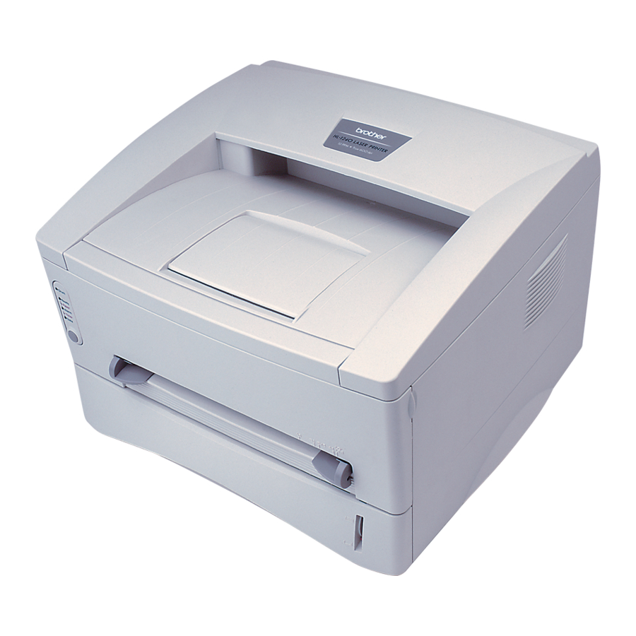
Brother 1240 Laser Printer Manuals
Manuals and User Guides for Brother 1240 Laser Printer. We have
1
Brother 1240 Laser Printer manual available for free PDF download: Service Manual
Brother 1240 Service Manual (243 pages)
Brother Laser Printer SERVICE MANUAL HL-1030, 1240, 1250, 1270N
Brand:
Brother
| Category:
Printer
| Size: 5.21 MB
Table of Contents
Table of Contents
4
Service Manual
1
Regulation
9
Safety Information
11
Chapter 1 General
13
Features
13
Overview
16
Specifications
17
Printing
17
Functions
18
Electrical and Mechanical
19
Feedable Paper
20
Network (for HL-1270N Only)
20
Paper
20
Paper Cassette Capacity
22
Print Delivery
22
Effective Printing Area
23
Print Guaranteed Area
23
Printing Area
23
Chapter 2 Installation and Basic Operation
25
Conditions Required for Installation
25
Environment
25
Power Supply
25
System Requirements for Brother Printer Solution for Windows
25
Unpacking
26
Install the Printer
27
For Windows Users
27
For Windows Users with no CD-ROM Drive
29
Install the Drum Unit
29
Load Paper
29
Print a Test Page
29
Connect the Printer and the Computer
30
Install the Printer Driver from Floppy Disk
30
Connect the USB Interface Cable
31
Install the USB Driver
31
Using the USB Interface
31
Using the USB Interface (for Windows 98 Only)
31
For Macintosh (Imac and Power Macintosh) with USB Users Only
33
Set the PC Printer Port
33
Paper Handling
34
Load Paper into the Paper Cassette
34
Load Paper Manually
34
To Print on both Sides of the Paper from the Paper Cassette
35
Two Side Printing (Manual Duplexing)
35
To Print on both Sides of the Paper from the Manual Feed Slot
36
Control Panel Operation
37
Ready (Paper) LED Indications
37
Alarm LED Indications
38
Data (Toner) LED Indications
38
Drum LED Indications
38
Control Panel Button Operations
39
Other Control Features
39
Sleep Mode
39
Test Print Mode
40
Network Board Operation (for Hl-1270N Only)
41
Connect the Ethernet Cable
41
Install the Bradmin32: Configuration Utility (for Windows 95/98/NT 4.0 Users Only)
41
Preparing the BR-Net Board
41
Factory Default Setting
42
Functions
42
LED Functions
42
Print Configuration Page
42
Chapter 3 Theory of Operation
43
Electronics
43
General Block Diagram
43
Main PCB Block Diagram
46
Asic
49
Main PCB
49
Rom
52
Dram
54
Flash ROM
54
Optional RAM
56
Optional Serial I/O
57
PCI Bus
57
Eeprom
58
Reset Circuit
58
Engine I/O
59
BR-Net PCB (for HL-1270 Only)
60
Engine PCB
60
Low-Voltage Power Supply
61
Power Supply
61
High-Voltage Power Supply
62
Mechanics
63
Overview of Printing Mechanism
63
Paper Registration
65
Paper Supply
65
Paper Transfer
65
Cover Sensors a and B
66
Paper Eject
66
Sensors
66
Cleaner
67
Drum Unit
67
Photosensitive Drum
67
Primary Charger
67
Toner Cartridge
67
Toner Sensor
67
Transfer Roller
67
Charging
68
Exposure Stage
68
Print Process
68
Developing
69
Fixing Stage
70
Transfer
70
Chapter 4 Disassembly and Re-Assembly
71
Safety Precautions
71
Disassembly Flow
72
Disassembly Procedure
73
AC Cord
73
Drum Unit
73
Paper Cassette
74
Network Board (for HL-1270N Only)
80
Front Cover
81
Top Cover
82
Main Cover
83
Laser Unit
85
Drive Unit
86
Fixing Unit
88
Base Plate
99
Lower Tray Relay PCB ASSY (for HL-1250/1270N Only)
101
Main PCB ASSY
101
Low-Voltage Power Supply PCB ASSY
102
Engine PCB ASSY / High-Voltage Power Supply PCB ASSY
104
Panel PCB ASSY
106
Solenoid ASSY
106
Fan Motor ASSY
109
Toner Sensor PCB ASSY (Light Emission)
110
Toner Sensor PCB ASSY (Light Reception)
110
Paper Pick-Up Roller ASSY
111
Paper Feed Roller ASSY
112
Outer Chute 1
113
Packing
114
Chapter 5 Periodic Maintenance
115
Consumable Parts
115
Drum Unit
115
Toner Cartridge
116
Periodical Replacement Parts
118
Periodical Cleaning
119
Cleaning the Drum Unit
119
Cleaning the Printer Exterior
119
Cleaning the Electrical Terminals
120
Cleaning the Scanner Window
120
Mtbf / Mttr
121
Chapter 6 Troubleshooting
123
Introduction
123
Initial Check
123
Warnings for Maintenance Work
124
Identify the Problem
125
Operator Calls & Service Calls
126
Operator Calls
126
Service Calls
126
Error Messages
128
Error Messages in the Status Monitor
128
Error Message Printouts
130
Paper Problems
131
Paper Load Problems
131
Clearing the Jammed Paper
132
Paper Jams
132
Causes & Countermeasures
133
Paper Feeding Problems
134
Software Setting Problems
136
Malfunctions
140
Image Defects
145
Image Defect Examples
145
Troubleshooting Image Defect
146
Drum Unit
163
Location of Grounding Contacts
163
Printer Body & Paper Cassette
163
Incorrect Printout
164
Network Problem (for Hl-1270N Only)
167
Installation Problem
167
Intermittent Problem
168
TCP/IP Troubleshooting
169
UNIX Troubleshooting
169
Windows 95/98 Peer to Peer Print (LPR) Troubleshooting
170
Windows NT/LAN Server (TCP/IP) Troubleshooting
170
Internet Print (TCP/IP) Troubleshooting
171
Windows 95/98 (or Later) Peer to Peer (HP Jetadmin Compatible Method) Troubleshooting
171
Windows 95/98/NT 4.0 Peer to Peer Print (Netbios) Troubleshooting
171
Appletalk Troubleshooting
172
Novell Netware Troubleshooting
172
Apple TCP/IP Printing (System 8.6 or Later)
173
Web Browser Troubleshooting (TCP/IP)
173
Inspection Mode
174
Test Print Mode
174
Inspection Mode
175
Serial No. Descriptions
179
Diameter / Circumference of Rollers
181
Print Speeds with Various Settings
182
How to Know Drum Unit Life & Page Counter
183
How to Use the Self-Diagnostics Tools
189
Nvram Default Value
193
Paper Cassette Information (for Europe Only
194
Connection Diagram, Hl-1030/1240
195
Connection Diagram, Hl-1250
196
Connection Diagram, Hl-1270N
197
Main Pcb Circuit Diagram, Hl-1030/1240 (1/2
198
Main Pcb Circuit Diagram, Hl-1030/1240 (2/2
199
Main Pcb Circuit Diagram, Hl-1250/1270N (1/5
200
Main Pcb Circuit Diagram, Hl-1250/1270N (2/5
201
Main Pcb Circuit Diagram, Hl-1250/1270N (3/5
202
Main Pcb Circuit Diagram, Hl-1250/1270N (4/5
203
Main Pcb Circuit Diagram, Hl-1250/1270N (5/5
204
Engine Pcb Circuit Diagram (Old
205
Engine Pcb Circuit Diagram (New
206
Network Board Circuit Diagram
207
Low-Voltage Power Supply Pcb Circuit Diagram (110 - 120V)
208
Low-Voltage Power Supply Pcb Circuit Diagram (220 - 240V)
209
High-Voltage Power Supply Pcb Circuit Diagram (Old
210
High-Voltage Power Supply Pcb Circuit Diagram (New
211
Differences between Old & New Versions of Hvps & Engine Pcb
212
Parts Reference List
219
Table of Contents
221
Frame / Drive Unit
222
Laser Unit
222
Paper Feeder
224
Fixing Unit
226
Paper Cassette
230
Covers
231
Main Pcb
234
Engine Pcb
235
Low-Voltage Power Supply Pcb
235
Ac Cords
237
High-Voltage Power Supply Pcb
237
Accessories
239
Network Board
241
Packing Materials
241
Adjusting Tool
243
Advertisement
Advertisement
Related Products
Brother 1435 - HL B/W Laser Printer
Brother 1470N - HL B/W Laser Printer
Brother 1440 - HL B/W Laser Printer
Brother P-Touch 1810
Brother 1270N
Brother 1670N - B/W Laser Printer
Brother 1870N - HL B/W Laser Printer
Brother P-touch 1750
Brother 1660e - B/W Laser Printer
Brother 1250
Brother Categories
Sewing Machine
All in One Printer
Printer
Label Maker
Fax Machine
More Brother Manuals
Login
Sign In
OR
Sign in with Facebook
Sign in with Google
Upload manual
Upload from disk
Upload from URL