Sign In
Upload
Manuals
Brands
Bosch Manuals
Control Panel
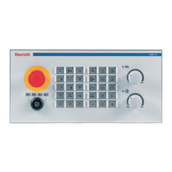
Rexroth VAM 10.1
Bosch Rexroth VAM 10.1 Manuals
Manuals and User Guides for Bosch Rexroth VAM 10.1. We have
1
Bosch Rexroth VAM 10.1 manual available for free PDF download: Project Planning Manual
Bosch Rexroth VAM 10.1 Project Planning Manual (64 pages)
Brand:
Bosch
| Category:
Control Panel
| Size: 2.56 MB
Table of Contents
English
3
Table of Contents
3
1 System Presentation
7
Brief Description
7
Machine Operator Panel VAM 10.1
8
Machine Operator Panel VAM 40.1
8
Use of the Machine Operator Panels in Residential Areas
8
2 Important Directions for Use
9
Appropriate Use
9
Introduction
9
Areas of Use and Application
10
Inappropriate Use
10
3 Safety Instructions for Electric Drives and Controls
11
Introduction
11
Explanations
11
Hazards by Improper Use
12
General Information
13
Protection against Contact with Electrical Parts
14
Protection against Electric Shock by Protective Low Voltage (PELV)
15
Protection against Dangerous Movements
16
Protection against Magnetic and Electromagnetic Fields During Operation and Mounting
17
Protection against Contact with Hot Parts
18
3.10 Protection During Handling and Mounting
18
3.11 Battery Safety
19
3.12 Protection against Pressurized Systems
19
4 Technical Data
21
Basic Device
21
Key Switch
22
Machine Pushbutton and E-STOP
23
Ambient Conditions
23
Used Standards
24
Compatibility Test
24
5 Dimensions
25
Housing Dimensions
25
Housing Dimensions VAM 10.1, Front, Side and Top View
25
Housing Dimensions VAM 10.1, Rear View
25
Installation
27
Installation Notes
27
Mounting Cut-Out
27
Mounting Dimensions VAM 10.1
28
Mounting Dimensions VAM 40.1
28
6 Module Layout
29
General Information
29
Labeling Templates for Slide-In Strips
29
Basic Device
29
Modules
32
Quick STOP Module
32
Further Modules
32
7 Interfaces
33
Connector Panel
33
Protective Earth Terminal
33
Current and Voltage Supply (X10)
34
Field Bus Interface PROFIBUS DP (X71)
35
General Information
35
Pin Assignment
35
Digital 24 V Inputs and Outputs (X21, X22, X11)
36
Pin Assignment (3 X 8-Pin Weidmüller Connector (3.5 Grid))
36
Characteristics of Digital Inputs
37
Characteristics of Digital Outputs
37
Connection for External Hand-Held Terminal (X81)
37
Connection for Internal Handwheel (X82)
39
8 Commissioning
41
GSD File
41
PROFIBUS DP Address Settings
42
Baud Rate Setting
43
Status Displays
43
Address Assignment
46
Keypads
46
Fig. 8-7: I/O Assignment of Module Keypad
46
Override Rotary Switch
47
Digital 24 V Inputs and Outputs
48
External Hand-Held Terminal
48
Internal Handwheel
48
Fig. 8-11: I/O Assignment of Module 16DI, 8DO
48
Fig. 8-12: Input Assignment for Module "Manual Control Unit
48
Fig. 8-13: Input Assignment for Module "Handwheel
48
Configuration Specification
49
Vam 10.1-Pb-Na-Ta-Ta-Vb-1608-Nn
49
Vam 40.1-Pb-Na-Ta-Ta-Vb-1608-Nn
49
Fig. 8-14: VAM 10.1-PB-NA-TA-TA-VB-1608-NN
49
Fig. 8-15: VAM 40.1-PB-NA-TA-TA-VB-1608-NN
49
Exemplary Configuration with Indralogic
50
9 Ordering Information
51
Type Code
51
Accessories
53
Deutsch
55
Fig. 3-1: Hazard Classification (According to ANSI Z535)
11
Fig. 4-1: General Technical Data
21
Fig. 4-2: Electrical Data
21
Fig. 4-3: Connection Method
21
Fig. 4-4: Contact Assignment of the Key Switch
22
Fig. 4-5: Technical Data of the Key Switch
22
Fig. 4-6: Technical Data for Machine Pushbutton and E-STOP
23
Fig. 4-7: Ambient Conditions
23
Fig. 4-8: Used Standards
24
Fig. 5-2: Housing Dimensions VAM 10.1, Rear View
25
Housing Dimensions VAM 40.1, Front, Side and Top View
26
Housing Dimensions VAM 40.1, Rear View
26
Fig. 5-3: Housing Dimensions VAM 40.1, Front, Side and Top View
26
Fig. 5-4: Housing Dimensions VAM 40.1, Rear View
26
Fig. 6-1: Basic Device
29
E-STOP and Key Switch
30
Keypads
30
Fig. 6-2: E-STOP and Key Switch
30
Fig. 6-3: Keypads
30
Override Rotary Switch
31
Fig. 6-4: Override Rotary Switch
31
Fig. 6-5: Quick STOP Module
32
Fig. 7-2: Pin Assignment X10
34
Fig. 7-3: Fuses
34
Fig. 7-4: Field Bus Interface PROFIBUS DP According to en 50170
35
Fig. 7-5: Pin Assignment of the PROFIBUS DP Interface
35
Fig. 7-6: Pin Assignment of the PROFIBUS DP Interface
35
Fig. 7-8: Characteristics of Digital Inputs
37
Fig. 7-9: Characteristics of Digital Outputs
37
Fig. 7-10: Pin Assignment X81
38
Fig. 7-11: Pin Assignment X81
38
Fig. 7-12: Characteristics of the Handwheel Interface
39
Fig. 7-13: Pin Assignment X81
39
Fig. 8-3: Status Displays
44
Fig. 8-4: Display of Status "System Stop
45
Fig. 8-5: Keypad TA
46
Fig. 8-6: I/O Assignment of Module Keypad
46
10 List of Figures
55
11 Service & Support
57
11.1 Helpdesk
57
11.2 Service-Hotline
57
11.3 Internet
57
Vor der Kontaktaufnahme
57
11.5 Kundenbetreuungsstellen
58
Sales & Service Facilities
58
Advertisement
Advertisement
Related Products
Bosch REXROTH IndraControl VAM 42.1
Bosch REXROTH IndraControl VAM 12.1
Bosch Rexroth VAM 10.2
Bosch Rexroth VAM 40.2
Bosch Rexroth VAM 40.1
Bosch Rexroth IndraControl VAM 11.1
Bosch Rexroth IndraControl VAM 41.1
Bosch Rexroth IndraControl VR2104 Singletouch
Bosch Rexroth IndraControl VCP 05
Bosch Rexroth IndraControl VDP 08.3
Bosch Categories
Dishwasher
Washer
Oven
Power Tool
Dryer
More Bosch Manuals
Login
Sign In
OR
Sign in with Facebook
Sign in with Google
Upload manual
Upload from disk
Upload from URL