Sign In
Upload
Manuals
Brands
Bosch Manuals
Control Panel
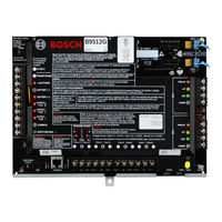
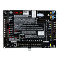
B8512G-E
User Manuals: Bosch B8512G-E IP Control Panel
Manuals and User Guides for Bosch B8512G-E IP Control Panel. We have
5
Bosch B8512G-E IP Control Panel manuals available for free PDF download: Program Entry Manual, Installation And System Reference Manual, Installation Manual
Bosch B8512G-E Program Entry Manual (284 pages)
Security System
Brand:
Bosch
| Category:
Control Panel
| Size: 3.08 MB
Table of Contents
Table of Contents
3
User Command
9
Remote Programming Software
17
Compliance Settings
18
SIA CP-01 Verification
18
ULC Compliance
19
CAN/ULC-S304 Compliance
19
CAN/ULC-S559, Required Programming
19
CAN/ULC-S559, Recommended Programming
22
UL864 Fire Application
26
Supervision Configuration
27
Panel Wide Parameters
28
Phone and Phone Parameters
28
Phone Destination 1 (to 4)
28
Phone Destination 1 (to 4) Format
28
DTMF Dialing
29
Phone Supervision Time
29
Alarm on Fail
29
Buzz on Fail
30
Two Phone Lines
30
Expand Test Report
30
PSTN Compatibility
31
On Board Ethernet (IP) Communicator
31
Ipv6 Mode
31
Ipv4 Dhcp/Autoip Enable
31
Ipv4 Address
32
Ipv4 Subnet Mask
32
Ipv4 Default Gateway
32
Ipv4 DNS Server IP Address
33
Ipv6 DNS Server IP Address
33
Upnp (Universal Plug and Play) Enable
33
ARP Cache Timeout (Sec.)
34
Module Hostname
34
TCP / UDP Port Number
34
TCP Keep Alive Time (Sec.)
35
Ipv4 Test Address
35
Ipv6 Test Address
35
Alternate Ipv4 DNS Server IP Address
35
Alternate Ipv6 DNS Server IP Address
36
Cellular Plug-In Module
36
Inbound SMS
36
Session Keep Alive Period (Min.)
36
Inactivity Timeout (Min.)
37
Reporting Delay for Low Signal Strength (Sec.)
37
Reporting Delay for no Towers (Sec.)
38
Outgoing SMS Length
38
Network Access Point Name (APN)
39
Network Access Point User Name
39
Network Access Point Password
39
Sim Pin
39
Cloud Remote Connect
40
Cloud Remote Connect (Ethernet)
40
Cloud Remote Connect (Cellular)
40
IP Cameras
40
Camera Name
41
Camera Name (Second Language)
41
URL or IP Address
41
Bosch Connected Cameras
41
RCP+ Port
42
Service Password
42
Supervision Period (Sec.)
42
Live (Video)
42
Port
42
Use HTTPS
43
User Name
43
Password
43
Reporting Overview
44
Report Routing
46
Fire Reports
51
Gas Reports
51
Burglar Reports
52
Personal Emergency Reports
52
User Reports
53
Test Reports
54
Diagnostic Reports
54
Output Reports
55
Auto Function Reports
55
RPS Reports
56
Point Reports
56
User Change Reports
57
Access Reports
57
Communicator, Overview
58
Primary Destination Device
59
Backup Destination Device
60
RG same Network Receiver
61
Time Synchronization
61
Enhanced Communication
62
Reporting Format
62
Network Address
62
Port Number
63
Receiver Supervision Time
63
Poll Rate (Sec.)
64
ACK Wait Time (Sec.)
66
Retry Count
66
AES Key Size
67
AES Encryption Key
67
SDI2 RPS / Enhanced Communication
67
Enable Enhanced Communication
67
RPS Address Verification
68
RPS Network Address
68
RPS Port Number
68
Answer RPS over Network
68
Power Supervision
69
AC Fail Time
69
Resend AC Fail
69
AC Fail Display
69
AC Fail / Restoral Report
69
AC Tag Along
70
AC / Battery Buzz
70
Battery Fail / Restoral Report
70
RPS Parameters
71
RPS Passcode
71
Log % Full
71
Contact RPS if Log % Full
71
RPS Call Back
72
RPS Line Monitor
72
Answer Armed
73
Answer Disarmed
73
RPS Phone
73
RPS Modem Speed
74
Miscellaneous
74
Duress Type
74
Cancel Reports
75
Call for Service Text - First Language
75
Call for Service Text - Second Language
75
On Site Authorization for Firmware Update
76
Enclosure Tamper Enable
76
Fire Summary Sustain
77
Fire Supervision Event Type
77
Fire Trouble Resound
77
Fire Drill Duration
78
Early Ambush Time
78
Second Ambush Code
78
Abort Window
78
Passcode Length
79
Swinger Bypass Count
80
Remote Warning
81
Crystal Time Adjust
81
Part on Output
81
Early Area Armed Output
81
Daylight Saving Time
82
Date Format
82
Date Delimiter
82
Time Format
82
Time Zone
83
Description
85
Sdix Connector Protocol
85
Ground Fault Detection
85
Personal Notification Destinations
85
SMS Phone # / Email Address
86
User Language
86
Method
86
Personal Notification Reports
87
Personal Notification Routing Attempts
87
Email Server Configuration
87
Email Server Name/Address
88
Email Server Port Number
89
Email Server Authentication/Encryption
90
Authentication User Name
90
Authentication Password
90
Area Wide Parameters
91
Area / Bell Parameters, Open / Close Options
91
Area Name Text
91
Area Name Text (Second Language)
91
Area on
92
Account Number
92
Force Arm/Bypass Max
93
Delay Restorals
93
Exit Tone
93
Exit Delay Time
94
Auto Watch
94
Restart Time
94
Duress Enable
96
Area Type
96
Two man Rule
98
Early Ambush
99
Fire Time
99
Fire Pattern
100
Burg Time
100
Burg Pattern
101
Gas Pattern
101
Single Ring
102
Bell Test
102
Account O/C
103
Area O/C
103
Disable O/C in Window
103
Auto Close
104
Fail to Open
104
Fail to Close
104
Latest Close Time
105
Restricted O/C
105
Part on O/C
106
Exit Delay Restart
106
All On- no Exit
106
Exit Delay Warning
107
Entry Delay Warning
107
Area Re-Arm Time
107
Area Arming Text
108
Area Name Text
108
Account Is on Text
108
Area # Is on Text
109
Area # Is Not Ready Text
109
Area # Is off Text
109
Keypads
110
Keypad Assignments
110
Keypad Name
110
Keypad Name (Second Language)
110
Keypad Type
110
Area Assignment
111
Keypad Language
111
Scope
111
Area in Scope
112
Passcode Follows Scope
112
Enter Key Output
113
Passcode Enter Function
113
Dual Authentication
114
Dual Authentication Duration
114
Assign Door
114
Trouble Tone
115
Entry Tone
116
Exit Tone
116
Arm Area Warning Tone
116
Close Door Warning Tone
116
Idle Scroll Lock
117
Function Lock
117
Abort Display
117
Cancel Display
118
Nightlight Enable
118
Nightlight Brightness
118
Silence Keypress Tone
118
Show Date and Time
118
Keypad Volume
119
Keypad Brightness
119
Disable Presence Sensor
119
Disable Token Reader
119
Enable Tamper Switch
120
Feature Button Option
120
Supervision
120
D125X Passcode [Esc] Option
121
Global Keypad Settings
121
A Key Response
121
A Key Custom Function
122
B Key Response
122
B Key Custom Function
123
C Key Response
123
Manual Silent Alarm Audible on Comm Trouble
124
C Key Custom Function
124
Comm Trouble Options
125
Global Wireless Keyfob
125
Keyfob Function a Custom Function
125
Keyfob Function B Custom Function
125
Keyfob Panic Options
126
Custom Functions
127
Custom Function Text
127
Custom Function Text (Second Language)
127
Functions
127
Shortcut Menu
130
Function
130
Set/Clear All
130
Address
131
Output Parameters
132
Area Wide Outputs
133
Alarm Bell
133
Fire Bell
133
Reset Sensors
134
Fail to Close/Part on Armed
134
Force Armed
135
Watch Mode
135
Area Armed
135
Area off
135
Area Fault
136
Duress Output
136
Part on Fault
136
Silent Alarm
137
Gas Bell
137
Panel Wide Outputs
137
AC Failure
137
Battery Trouble
138
Phone Fail
138
Comm Fail
138
Log % Full
138
Summary Fire
139
Summary Alarm
139
Summary Fire Trouble
139
Summary Supervisory Fire
140
Summary Trouble
140
Summary Supervisory Burg
141
Summary Gas Output
141
Summary Gas Supervisory Output
141
Summary Gas Trouble Output
142
Output Configuration
142
Output Source
142
Output Text
143
Output Text (Second Language)
143
Hide from User
143
User Configuration
145
User Assignments (Passcodes)
145
User Name
145
Passcode
145
Remote Access
145
User Group
146
Area Authorities
146
Site Code
147
Card Data
147
Inovonics Keyfob RFID (B820)
147
RADION Keyfob RFID (B810)
148
Supervised
148
User Language
148
User Groups
149
User Group Name
149
User (Keypad) Functions
149
All On, Delay
149
All On, Instant
149
Part On, Instant
150
Part On, Delay
150
Watch Mode
150
View Area Status
150
View/Delete Event Memory
151
View Point Status
151
Walk Test (All Non-Fire Burg Points)
151
Walk Test All Fire Points
151
Send Report (Test/Status)
152
Door Control
152
Set Keypad Brightness / Volume / Keypress
152
Set/Show Date and Time
152
Change Passcodes
153
Add/Edit User
153
Delete User
153
Extend Close
153
View Event Log
154
User Command 7
154
Bypass a Point
154
Unbypass a Point
154
Reset Sensor
155
Change Output
155
Remote Program
155
Go to Area
156
Display Panel Type and Revision
156
Service Walk All Points
156
Change Skeds
156
Keypad Programming
157
Walk Test All Invisible Burg Points
157
Silence Function
157
Custom Function
157
Authority Levels
158
Authority Level Name
158
Authority Level Name (Second Language)
158
Disarm Select
158
All On, Delay
159
All On, Instant
159
Part On, Instant
160
Part On, Delay
160
Watch Mode
160
View Area Status
161
View Event Memory
161
View Point Status
161
Walk Test (All Non-Fire Burg Points)
161
Walk Test All Fire Points
162
Walk Test All Invisible Burg Points
162
Service Walk All Points
163
Send Report (Test / Status)
163
Cycle Door
164
(Un)Lock Door
164
Secure Door
164
Change Keypad Display
165
Change Date and Time
165
Change Passcodes
165
Add User Passcodes / Card / Level
165
Delete User Passcode / Card/ Level
166
Extend Close
166
View Event Log
166
User Command 7
166
User Command 9
167
Bypass a Point
167
Unbypass a Point
167
Reset Sensor(S)
167
Change Output(S)
168
Remote Program
168
Go to Area
168
Display Panel Type and Revision
169
Change Skeds
169
Custom Function
169
Force Arm
170
Send Area Open/Close
170
Restricted Open/Close
170
Part on Open/Close
171
Send Duress
171
Arm by Passcode
171
Disarm by Passcode
172
Security Level
172
Disarm Level
173
Function Level
173
Keyfob Arm
174
Keyfob Disarm
174
Firmware Update
175
Silence Function
175
Points
176
Point Assignments
176
Source
176
Text
176
2Nd Language Text
177
Profile (Index)
177
Profile (Index) Description
178
Area
178
Debounce
178
Output
179
Radion Rfid (B810)
179
RADION Device Type
180
Inovonics RFID (B820)
181
Cross Point Parameters
181
Cross Point Timer
181
Point Profiles
182
Point Profile Text (First Language)
182
Point Profile Text (Second Language)
183
Point Response Overview
183
Point Type
184
Point Response
184
Entry Delay
190
Entry Tone off
191
Silent Bell
191
Ring until Restored
192
Audible after Two Fails
192
Invisible Point
192
Buzz on Fault
193
Watch Point
193
Output Response Type
194
Display as Device
194
Local While Disarmed
194
Local While Armed
195
Disable Restorals
195
Force Arm Returnable
196
Bypass Returnable
196
Bypassable
196
Swinger Bypass
197
Report Bypass at Occurrence
197
Defer Bypass Report
197
Cross Point
198
Alarm Verify
199
Resettable
199
Alarm Abort
199
Custom Function
200
Monitor Delay
200
Wireless Point Supervision Time
200
Delay Response, Disarmed
201
Delay Response, Armed
201
Circuit Style
202
Normal State
202
Point Profile Descriptions
203
24-Hour
203
Part on
203
Interior
204
Interior Follower
204
Keyswitch Maintained
205
Keyswith Momentary
205
Open / Close Point
205
Fire Point
206
Aux AC Supervision
206
Advertisement
Bosch B8512G-E Installation And System Reference Manual (186 pages)
Brand:
Bosch
| Category:
Control Panel
| Size: 4.89 MB
Table of Contents
Table of Contents
3
Certifications, Approvals, Listings, and Safety
9
Listings and Approvals
9
Ulc
9
Security Industry Association (SIA)
9
Department of Defense (Dod)
9
Department of Energy
9
National Institute of Standards and Technology (NIST)
9
Federal Communications Commission (FCC) Rules
10
Industry Canada (IC)
10
Lightning
10
Effects of Lighting
11
Installation Precautions
11
Warranty
11
Introduction
12
About Documentation
12
Related Documentation
12
Bosch Security Systems, Inc. Product Manufacturing Dates
14
System Overview
15
Configuration and Parts
16
Control Panel Capacities
16
Parts List
16
Order Separately
17
Accessories
17
Compatible UL Listed Synchronization (Sync) Modules and Strobes
22
Features
27
SDI2 Interconnect Wiring
27
Points
27
Areas and Accounts
28
Digital Communication
28
Keypads
28
Events
28
Programming
29
Firmware Updates
29
Access Control
29
Ground Fault Detection
29
Dual Authentication
29
Installation Checklist
30
Control Panel Installation
31
Install the Enclosure
31
Install the Control Panel
32
Mount the Control Panel
32
Connect Earth Ground
32
Ground Fault Detect Enable
32
Ground Fault Detection Troubleshooting
33
Control Panel to Module Wiring Overview
33
Install the Transformer
36
Power Supply
36
Primary (AC) Power
36
Secondary (DC) Power
37
Install the Battery
37
Battery Status Led
38
Battery Maintenance
39
Battery Supervision
39
Battery Charging Circuit Float Charge
39
Battery Discharge and Recharge Schedule
40
B520 Auxiliary Power Supply
40
SDI2 Address Settings
41
Supervision
41
Auxiliary Power Supply Trouble Conditions
41
Installation and Control Panel Wiring (B520)
41
Powered Device and Battery Wiring
42
Telephone Communications
44
B430 Plug-In Telephone Communicator
44
Supervision
44
Installation and Module Wiring (B430)
44
Diagnostic Leds
45
Phone Jack Location
45
Telephone Line Monitor
46
Called Party Disconnect
46
Communication Failure
47
IP Communications
48
On-Board Ethernet Connection
48
Supervision
48
Local RPS Programming
48
On-Board Ethernet Diagnostic Leds
49
Conettix Plug-In Cellular Communicators
50
Supervision
50
Installation and Module Wiring (B44X)
50
Signal Strength and Diagnostic Leds
51
B426 Ethernet Communication Module
52
Address and Emulation Settings
52
Supervision
52
B426 Module Faults
52
Local RPS Programming
53
Installation and Control Panel Wiring (B426)
53
Diagnostic Leds
54
B450 Conettix Plug-In Communicator Interface
55
SDI2 Address Settings
56
Supervision
56
Installation and Control Panel Wiring (B450)
56
Diagnostic Leds
57
Compatible Receivers for IP Communication
57
Keypads, Keyswitches, Keyfobs and Transmitters
59
Keypads
59
B915 Basic Keypad
59
B920 Two-Line Alphanumeric Keypad
59
B921C Two-Line Capacitive Keypad with Inputs
60
B925F Fire Keypad
60
B926F Keypad
60
B930 ATM Style Alphanumeric Keypad
60
B942 Touch Screen Keypad
60
SDI Keypads
60
Shortcuts and Custom Functions
60
Address Settings
61
Supervision
61
Installation and Control Panel Wiring (Keypads)
61
Sensor Loops Overview and Wiring (B921C/B942/B942W Only)
62
Output Wiring (B942/B942W Only)
63
Troubleshooting
63
Keyswitches
63
Operation
64
Installation and Control Panel Wiring (Keyswitches)
64
RADION Keyfobs and Inovonics Pendant Transmitters
65
On-Board Outputs
66
Circuit Protection
66
Total Available Power
66
Continuous Power Outputs
67
Programmable Power Outputs
67
Terminals 6 and 7
67
Terminal 8
68
USB Power
68
Off-Board Outputs
69
B308 Octo-Output Module
69
SDI2 Address Settings
69
Supervision
69
Installation and Control Panel Wiring (B308)
70
B600 Retrofit ZONEX Module
70
D8129 Octo-Relay Module
70
On-Board Points
72
Point Sensor Loops
72
Single EOL (and no EOL) Resistor Circuit Style
72
Dual EOL Resistor Circuit Style
73
Point Response Time
74
Off-Board Points
75
B208 Octo-Input Module
75
SDI2 Address Settings
75
Supervision
75
Installation and Control Panel Wiring (B208)
75
Sensor Loops Overview and Wiring
76
B299 POPEX Module
78
SDI2 Address Settings
78
Supervision
78
Installation and Control Panel Wiring (B299)
79
POPIT Devices Overview and Wiring
79
D8125 Expansion
80
B600 Retrofit ZONEX Module
80
D8128D Octopopit Eight-Point Expander
81
Test Off-Board Points
81
Extra Point Events
82
Missing Point Conditions
82
Wireless Modules
83
B810 Receiver
83
SDI2 Address Settings
83
Supervision
83
Installation and Control Panel Wiring (B810)
83
B820 SDI2 Inovonics Interface Module
84
SDI2 Address Settings
84
Supervision
84
Installation and Control Panel Wiring (B820)
84
Access Control
86
B901
86
Address Settings
86
Supervision
86
Installation and Control Panel Wiring (B901)
86
D9210C
87
Card Reader Wiring
87
Program and Test the Control Panel
88
Program the Control Panel
88
Perform Walk Tests
88
Fire Walk Test
88
Intrusion Walk Test
88
Service Walk Test
89
Invisible Walk Test
89
Control Panel Board Overview
91
System Wiring Diagrams
93
Power Supply Side Wiring
94
Input Points Wiring with D125B, D130, or D129
95
Input Points Wiring with or Without EOL Resistors
95
SDI and ZONEX Wiring
96
SDI2 Devices General System Wiring
98
SDI2 Bus Wiring Recommendations
98
2-Wire Smoke Wiring (D125B)
100
Bosch B8512G-E Installation Manual (185 pages)
Brand:
Bosch
| Category:
Control Panel
| Size: 5.75 MB
Table of Contents
Table of Contents
3
Certifications, Approvals, Listings, and Safety
9
Listings and Approvals
9
Ulc
9
Security Industry Association (SIA)
9
Department of Defense (Dod)
9
Department of Energy
9
National Institute of Standards and Technology (NIST)
9
Federal Communications Commission (FCC) Rules
10
Industry Canada (IC)
10
Safety
11
Lightning
11
Earth Ground
11
Power
12
Introduction
13
About Documentation
13
Related Documentation
13
Bosch Security Systems, Inc. Product Manufacturing Dates
15
System Overview
16
Parts List
16
Control Panel Capacities
16
Features
17
SDI2 Interconnect Wiring
17
Points
17
Areas and Accounts
17
Digital Communication
18
Keypads
18
Events
18
Programming
19
Firmware Updates
19
Access Control
19
Ground Fault Detection
19
Dual Authentication
19
Recent Closing
20
Accessories
20
Compatible UL Listed Synchronization (Sync) Modules and Strobes
25
Installation Checklist
30
Control Panel Installation
31
Installing the Enclosure
31
Installing the Control Panel
31
Earth Ground
32
Ground Fault Detect Enable
32
Ground Fault Detection Troubleshooting
32
Control Panel to Module Wiring Overview
33
Power Supply
36
Secondary (DC) Power
36
Install the Battery
36
Battery Status Led
37
Battery Maintenance
38
Battery Supervision
38
Battery Charging Circuit Float Charge
38
Battery Discharge and Recharge Schedule
39
B520 Aux Power Supply
39
SDI2 Address Settings
40
Supervision
40
Auxiliary Power Supply Trouble Conditions
40
Installation and Control Panel Wiring (B520)
40
Powered Device and Battery Wiring
41
Telephone Communications
44
B430 Plug-In Communicator, Telephone
44
Supervision
44
Installation and Module Wiring (B430)
44
Diagnostic Leds
45
Phone Jack Location
45
Telephone Line Monitor
46
Called Party Disconnect
46
Communication Failure
47
IP Communications
48
On-Board Ethernet Connection
48
Supervision
48
Local Programming
48
On-Board Ethernet Diagnostic Leds
49
Conettix Plug-In Cellular Modules
50
B426 Ethernet Communication Module
50
Address and Emulation Settings
50
Supervision
50
B426 Module Faults
51
Installation and Control Panel Wiring (B426)
51
Diagnostic Leds
52
Local Programming
53
B450 Conettix Plug-In Communicator Interface
54
SDI2 Address Settings
54
Supervision
54
Installation and Control Panel Wiring (B450)
54
Diagnostic Leds
55
Compatible Receivers for IP Communication
56
Keypads, Keyswitches, Keyfobs and Transmitters
58
Keypads
58
Keypads Overview
58
B921C Two-Line Capacitive Keypad with Inputs
59
Shortcuts and Custom Functions
59
Address Settings
60
Supervision
60
Installation and Control Panel Wiring (Keypads)
60
Sensor Loops Overview and Wiring (B921C/B942/B942W Only)
61
Output Wiring (B942/B942W Only)
62
Troubleshooting
62
Keyswitches
62
Operation
63
Installation and Control Panel Wiring (Keyswitches)
63
RADION Keyfobs and Inovonics Pendant Transmitters
64
On-Board Outputs
65
Circuit Protection
65
Total Available Power
65
Continuous Power Outputs
66
Programmable Power Outputs
66
Terminals 6 and 7
66
Terminal 8
67
USB Power
67
Off-Board Outputs
68
B308 Octo-Output Module
68
SDI2 Address Settings
68
Supervision
68
Installation and Control Panel Wiring (B308)
69
B600 Retrofit ZONEX Module
69
Installation and Control Panel Wiring (B600)
70
D8129 Octo-Relay Module
71
On-Board Points
72
Point Sensor Loops
72
Single EOL (and no EOL) Resistor Circuit Style
72
Dual EOL Resistor Circuit Style
73
Point Response Time
74
Off-Board Points
75
B208 Octo-Input Module
75
SDI2 Address Settings
75
Supervision
75
Installation and Control Panel Wiring (B208)
75
Sensor Loops Overview and Wiring
77
B299 POPEX Module
79
SDI2 Address Settings
79
Supervision
79
Installation and Control Panel Wiring (B299)
80
POPIT Devices Overview and Wiring
80
B600 Retrofit ZONEX Module
81
Installation and Control Panel Wiring (B600)
81
D8125 Expansion
82
D8128D Octopopit Eight-Point Expander
83
Off-Board Points Test
84
Extra Point Events
84
Missing Point Conditions
84
Wireless Modules
85
B810 Receiver
85
SDI2 Address Settings
85
Supervision
85
Installation and Control Panel Wiring (B810)
85
B820 SDI2 Inovonics Interface Module
86
SDI2 Address Settings
86
Supervision
86
Installation and Control Panel Wiring (B820)
86
Access Control
88
B901 Door Controller
88
Address Settings
88
Supervision
88
Installation and Control Panel Wiring (B901)
89
D9210C Access Control Interface Module
89
Card Reader Wiring
90
Program and Test the Control Panel
91
Program the Control Panel
91
Program the Control Panel with RPS
91
Program the Control Panel with the Installer Services Portal Programming Tool
92
Program the Control Panel with a Keypad
92
Walk Tests
92
Fire Walk Test
92
Intrusion Walk Test
93
Service Walk Test
93
Invisible Walk Test
94
Control Panel Board Overview
95
System Wiring Diagrams
97
Power Supply Side Wiring
98
Input Points Wiring with D125B, D130, or D129
99
Input Points Wiring with or Without EOL Resistors
99
SDI and ZONEX Wiring
100
SDI2 Devices General System Wiring
102
SDI2 Bus Wiring Recommendations
102
2-Wire Smoke Wiring (D125B)
104
Advertisement
Bosch B8512G-E Installation Manual (47 pages)
Brand:
Bosch
| Category:
Control Panel
| Size: 2.93 MB
Table of Contents
About Documentation
3
Related Documentation
3
System Overview
6
Parts List
6
Control Panel Capacities
6
Control Panel Installation
8
Installing the Enclosure
8
Installing the Control Panel
8
Earth Ground
9
Ground Fault Detect Enable
9
Ground Fault Detection Troubleshooting
9
Control Panel to Module Wiring Overview
10
Power Supply
13
Secondary (DC) Power
13
Install the Battery
13
Battery Maintenance
15
Battery Supervision
15
Battery Charging Circuit Float Charge
16
Battery Discharge and Recharge Schedule
16
B520 Aux Power Supply
16
SDI2 Address Settings
17
Auxiliary Power Supply Trouble Conditions
17
Powered Device and Battery Wiring
18
Total Available Power
21
Continuous Power Outputs
22
Programmable Power Outputs
22
Usb Power
23
Control Panel Board Overview
24
System Wiring Diagrams
25
Power Supply Side Wiring
26
Input Points Wiring with or Without EOL Resistors
27
SDI and ZONEX Wiring
28
SDI2 Devices General System Wiring
30
SDI2 Bus Wiring Recommendations
30
2-Wire Smoke Wiring (D125B)
32
Earth Ground Wiring
33
Specifications
39
Wire Requirements
40
Bosch B8512G-E Installation Manual (41 pages)
Brand:
Bosch
| Category:
Control Panel
| Size: 1.54 MB
Table of Contents
ULC Installation Guide
3
Keypads
3
Transformers
3
Wiring
4
Requirements
4
Fire Monitoring Communication Systems
8
Programming
8
Protecting the Control Panel – Burglary
8
User Information
9
Compatibilities
9
Input Point Wiring Diagrams
15
ULC Listed Seismic Detector
17
ULC Commercial Motion Detector with Tamper
17
ULC Commercial Door/Window Contact
17
Double EOL Input for One Form C Contact
17
Fire Monitoring Communication Systems Wiring Diagrams
18
Dual Dialer Passive Communication System
19
IP Communication Systems (On-Board IP)
19
Control Panel with 2 B430 (PSTN) Modules
19
Control Panel with On-Board IP
19
IP Communication System (SDI2 IP)
20
PSTN/IP Communication System (On-Board IP)
20
Control Panel with a B426 Module
20
Control Panel with On-Board IP and a 430 (PSTN) Module
20
PSTN/IP Communication System (SDI2 IP)
21
Cellular Communication System
21
Control Panel* with a B44X (Cellular) Module
21
Cellular/Ip Communication System (On-Board IP)
22
Pstn/Cellular Communication System
22
Pstn/Cellular Communication System (SDI2 Cellular)
23
Off-Board Cellular Passive Communication System
24
B Series Sounder Wiring Diagram
25
Keypad Segment Test
26
Required Programming
27
Fire Cancel
27
POINTS > Point Assignments
29
Point Type Response and Circuit Style
29
Fire Panel Supervisory
29
Report Routing
30
SDI2 Device Failure
31
Primary Destination Device
31
Recommended Programming
32
Enhanced Communication Parameters
32
Advertisement
Related Products
Bosch B8512G
Bosch B9512G
Bosch B3512
Bosch B5512E
Bosch B4512E
Bosch B3512E
Bosch B9512G-E
Bosch B6512
Bosch BT220
Bosch Radion B810
Bosch Categories
Dishwasher
Washer
Oven
Power Tool
Dryer
More Bosch Manuals
Login
Sign In
OR
Sign in with Facebook
Sign in with Google
Upload manual
Upload from disk
Upload from URL