Table of Contents
Advertisement
Quick Links
GE Consumer & Industrial
Power Protection
Product Description
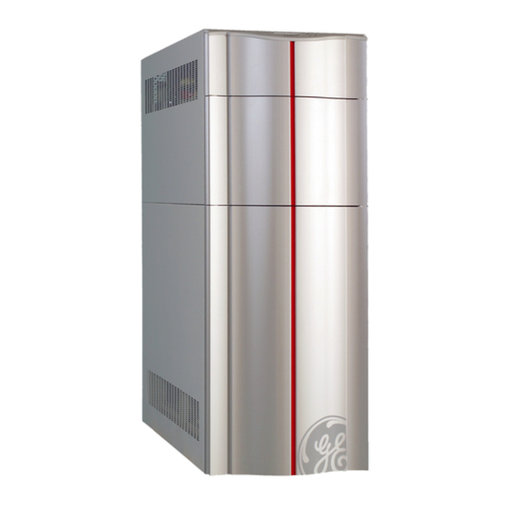
Digital Energy™ Uninterruptible Power Supply
LP 31 Series / 8 – 10 – 15 – 20 kVA
400 VAC CE / Series 1
Manufactured by:
GE Consumer & Industrial SA
General Electric Company
CH – 6595 Riazzino (Locarno)
Switzerland
T +41 (0)91 / 850 51 51
F +41 (0)91 / 850 51 44
www.gedigitalenergy.com
GE imagination at work
Advertisement
Table of Contents

Summary of Contents for GE Digital Energy LP 31 Series
-
Page 1: Product Description
Digital Energy™ Uninterruptible Power Supply LP 31 Series / 8 – 10 – 15 – 20 kVA 400 VAC CE / Series 1 Manufactured by: GE Consumer & Industrial SA General Electric Company CH – 6595 Riazzino (Locarno) Switzerland T +41 (0)91 / 850 51 51 F +41 (0)91 / 850 51 44 www.gedigitalenergy.com... -
Page 2: Table Of Contents
6.2 Alarm Boxes ......................................10 6.3 Connectivity Products..................................10 6.4 Battery Extension Packs ................................... 10 COPYRIGHT © 2005 by GE Consumer & Industrial Data subject to change without prior notice. All brands and product names are Trademarks or Registered Trademarks of their respective owners. -
Page 3: Introduction
1. INTRODUCTION The LP 31 Series / 8 – 10 – 15 - 20 kVA UPS series is a compact, truly On-line 3-phase in 1-phase out system which incorporates the most advanced power electronics technology to provide exceptional protection for electrical equipment. 2. -
Page 4: Normal Conditions
2.2 Normal Conditions Under normal input conditions (see section 4.2) energy from the mains is channelled through the input converter, which supplies the output converter and, together with the battery charger, keeps the battery fully charged. Surges and spikes are blocked completely at the input converter and very unstable mains can be supported. -
Page 5: Bypass Operation
2.4 Bypass operation The static switch provides transfer of the load to the line voltage without any interruption of the supply. The transfer is initiated by a signal from the output converter protection circuit in case of an overload, high temperature or output converter failure. When the conditions return to normal the load is automatically transferred back to the output converter. -
Page 6: External Description
3. EXTERNAL DESCRIPTION 3.1 Front and Rear Panel Figure 4 - Front and rear panel / 8-10-15-20 kVA UPS LP 31 Series FRONT REAR Operation/Alarm : green/red LED Interfaces: - ComConnect (RS232) LCD screen: 2 x 16 characters - Potentialfree contacts Push-buttons: down/enter-reset/up - CardConnect slot... -
Page 7: Alarm Conditions
The ‘default screen’ shows UPS model and actual load (values are examples): LP 15-31 LOAD 37% The 'information screens' show the UPSs system data: - Mains voltage, mains frequency and the power delivered by the mains. - Output voltage and output frequency, and the power delivered by the UPS. - Power factor, crest factor and peak currents of the connected equipment. -
Page 8: Standard Features
4. STANDARD FEATURES Automatic (quick) battery test The LP Series family UPS conducts periodic automatic battery tests to ensure that the batteries and the wiring are healthy and able to support power failures. The tests do not cause any interruption in the function of the unit. Automatic tests are conducted after every 500 operating hours. -
Page 9: Interfacing
Novell, UNIX, VMS, Banyan Vines, Windows 3/95/98/NT, Apple, IBM LANserver, IBM AS/400. Remote servicing through a modem (external) is possible with GE Victron SerVICe Software. We strongly recommend to use only original GE software products in combination with the ComConnect interface port. -
Page 10: Potential Free Contact Interface
5.2 Potential Free Contact Interface Four potential free change-over contacts are available for signalling the following alarms to a user defined system: • bypass active; • mains failure; • battery low; • general alarm. Capacity of the relay contacts: Nom: 48V 500mA Min: 5V 100mA...


